
High power control for sensitive contacts

The described circuits A and B demonstrate fundamental configurations for controlling resistive loads through the manipulation of contact states. In circuit A, the load is energized only when the actuating contact is closed, effectively creating a straightforward on/off control mechanism. Conversely, circuit B operates in a manner that energizes the load when the contact is open, providing a unique control behavior that may be useful in specific applications where reverse activation is required.
Both circuits can be adapted for latching functionality by utilizing a DC power supply instead of the specified AC supply. This modification allows the circuits to maintain their state (either on or off) even after the actuating contact is released, which can be advantageous in applications requiring persistent load activation without continuous input.
The operational parameters of these circuits are designed for low-power applications, with the voltage across the sensitive contacts maintained below 5 volts and the contact current limited to under 5 mA. This design consideration ensures compatibility with delicate components and enhances the longevity and reliability of the circuit.
For applications involving inductive loads, it is recommended that the resistor Rl be connected to the opposite side of the load, as illustrated in circuit C. This configuration helps to manage the back EMF generated by inductive loads, protecting the circuit components from potential damage and ensuring stable operation. The careful arrangement of these components allows for effective control of both resistive and inductive loads, accommodating various operational requirements in electronic designs.Two simple arrangementsfor resistive loads are shown in A & B. The circuit in A will provide load power when the actuating contact is closed, and no power when the contact is open. B provides the reverse of this action-power being supplied to the load when the contact is open with no load power when the contact is closed
If desired, both circuits can be made to latch by operating with dc instead of the indicated ac supply. In both of these circuits, voltage across the sensitive contacts is under 5 volts, and contact current is below 5 mA.
For inductive loads, Rl would normally be returned to the opposite side of the load as shown in C.
Related Circuits
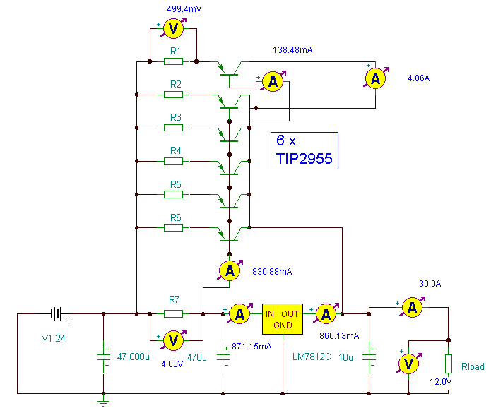
This power supply utilizes a single 7812 integrated circuit (IC) voltage regulator in conjunction with multiple external pass transistors to provide output load currents of up to 30 amps. The circuit design incorporates a 7812 voltage regulator, which is known...
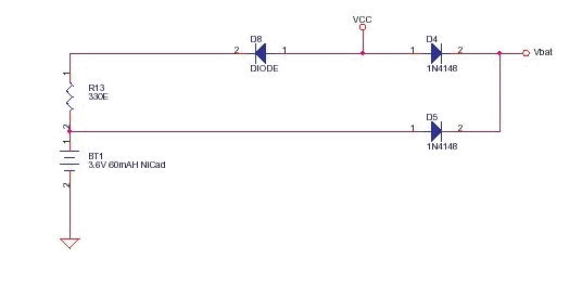
This circuit functions as a low-cost battery backup solution for SRAM and microcontroller/microprocessor applications. It utilizes 1N4148 diodes to prevent battery discharge back to the power source. Diode D8 provides a one-way path for charging the battery through resistor...
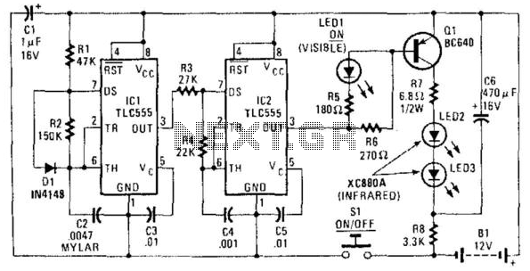
The transmitter is constructed using two CMOS 555 timer ICs (TLC 555s). It generates a modulated 35-kHz infrared signal. The carrier frequency of 35 kHz is produced by IC2, while IC1 generates a 1,500-Hz modulating signal. The output from...

Voltage variations and power cuts adversely affect various equipment such as TVs, VCRs, music systems, and refrigerators. This simple circuit will protect costly equipment from high and low voltages and voltage surges when power resumes. It also produces a...
The microcontroller-based water level controller and motor protector manages the on and off states of the motor based on the water level in the overhead tank (OHT). It regulates the tank's water level through a microcontroller, thereby providing automatic...
Most inverters available in the market utilize a modified sine wave to achieve better output at a competitive cost. The modified sine wave unit employs a 50% fixed PWM square wave, with the peaks balanced by a capacitor to...