
AD8531 IC For LCD Panel Backlight Automatic Control Circuit

The AD8531 is a precision operational amplifier that is well-suited for applications requiring high accuracy and low noise. In the context of an LCD panel backlight automatic control circuit, the AD8531 can be employed to regulate the brightness of the backlight based on ambient light conditions or other input parameters.
The circuit typically includes a light sensor, such as a photodiode or phototransistor, which detects the surrounding light levels. The output from the light sensor is fed into the non-inverting input of the AD8531. The operational amplifier processes this input signal and provides a corresponding output voltage that controls the backlight brightness via a pulse-width modulation (PWM) signal or a direct voltage control method.
In addition to controlling brightness, the AD8531's capability to compensate for aging effects is particularly beneficial in maintaining consistent performance over time. Aging can lead to variations in the output of the backlight, and by incorporating feedback mechanisms and reference voltages, the circuit can adjust the output to counteract these variations.
The design may also include additional components such as resistors, capacitors, and possibly a microcontroller to manage the overall operation and enhance functionality. Proper selection of these components is crucial for achieving optimal performance and stability in the automatic control of the LCD panel backlight.
This circuit design is ideal for applications in environments where lighting conditions fluctuate, ensuring that the LCD display remains readable and energy-efficient.The following circuit shows about AD8531 IC For LCD Panel Backlight Automatic Control Circuit. Features: can compensate for aging effects and the . 🔗 External reference
Related Circuits
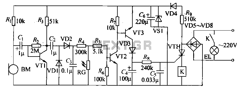
The voice circuits discussed in this section operate such that during daylight or in bright conditions, the voice-activated switch remains off, preventing the lamp from lighting. Conversely, in low-light conditions or at night, the sound control switch is activated....
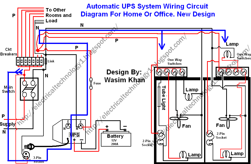
This wiring circuit diagram is designed for providing power to specific rooms in a home or office during a power supply failure. It ensures continuous power supply to devices such as laptops and computers in those particular rooms, especially...
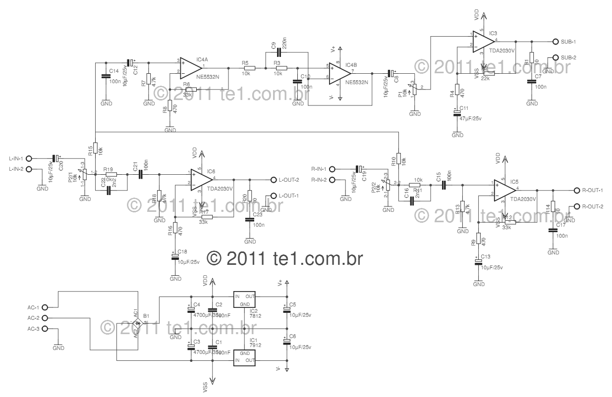
This circuit is a complete application for a 2.1 amplifier system, consisting of two satellite speakers powered by a TDA2030 and one subwoofer. This 2.1 system is commonly utilized in commercial applications as an amplifier for computers, enhancing audio...
This circuit is a conventional Pierce-type oscillator that utilizes a JFET. It operates with fundamental mode crystals, offering decent performance and reliability when a low noise JFET is employed. The feedback is regulated by the capacitance of C1 from...
The circuit consists of a lag comparator with amplifier A1 and an inverting integrator A2. The charging and discharging time constant is determined by the integral resistors (R1 + RP1) and the capacitor C1. Diodes VD1 to VD5 form...
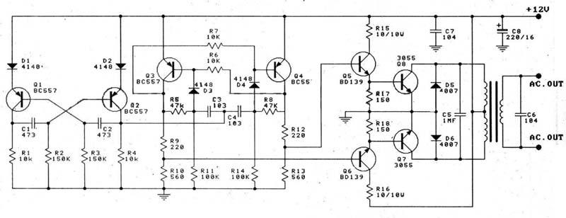
This circuit is a 100W DC inverter based on a transistored multivibrator and serves as a transistor signal amplifier. The inverter converts a 12V DC input voltage to approximately 220V AC. It is recommended to use a 12V car...