
6 static display circuit

The static display circuit utilizes the 74LS244 as bus drivers to manage data flow to multiple display units. Each unit consists of an LED display latch, specifically the 74LS273, which is responsible for holding the data that will be visually represented. The connection between the data bus and the latches is facilitated by the 74LS244, which ensures that the data is transmitted accurately when the appropriate control signals are activated.
The address decoder, 74LS138, plays a critical role in this circuit by determining which latch should receive the data from the bus. It decodes the address signals and enables the corresponding latch based on the decoded output. The simultaneous activation of the IOW (Input/Output Write) signal and the A9 address line, both being low, triggers the 74LS244 to become operational. This configuration allows for precise control over which display is updated at any given time.
The sequential addressing of the display bits, ranging from 100H to 105H, indicates that there are six distinct latches in the circuit, each capable of holding its own data. When the control signals are correctly set, the 74LS244 transmits the relevant data from the data bus to the selected latch, allowing the LED display to reflect the intended output. This setup is particularly useful in applications requiring multiple visual outputs, such as scoreboards or status indicators, where real-time data representation is crucial.6 shows the static display circuit. Figure, 74LS244 as bus drivers, six figures show a public bus, each with an LED display martyrdom latch (such as 74LS273) connected to the code for latching display data to be displayed. Data is displayed on behalf of code from the data bus via 74LS244 to the input of each latch, recanalization specified by the address decoder 7,415,138± latch latches. 74LS244 bus driver by the IOW and A9 control, when the output instruction is executed so that Lai) W and Ag at the same time is low, 74LS244 to play on, transmitting data on the data bus corresponding to each display latches (74LS273) on.
In the circuit shown in the figure, from left to right each display bit address followed 100H, 101H, 10ZH, 103H, 104H, 105H.
Related Circuits
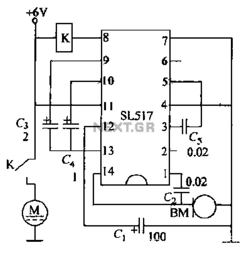
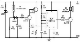
Electric cars utilize a voice circuit principle, where sound signals are captured by a microphone (BM) and processed. The signal is then coupled through a capacitor to an integrated circuit (IC), which includes an internal amplifier that boosts the...
NOTE: There is no guarantee as to the suitability of said circuits and information for any purpose whatsoever other than as a self-training aid. I.E. If it blows your equipments, trashes your hard disc, wipes your backup, burns your...
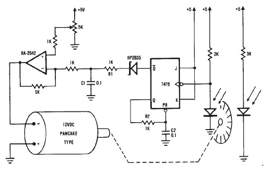
A simple encoder circuit for a DC motor can be constructed using this circuit diagram. The system consists of the HA-2542, a small 12-V DC motor, and a position encoder. During operation, the encoder generates a series of constant-width...
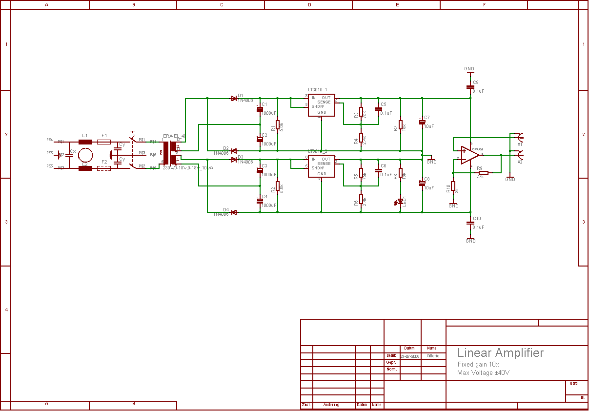
The aim of this project was to develop a linear analogue amplifier designed for laboratory use. This amplifier has to realise a voltage amplification of 10x and is intended to amplify function generator signals for tests. Power supply requirements:...
Fire alarm circuit using an LDR (Light Dependent Resistor) as a flame sensor. It warns the user about fire accidents by detecting smoke produced during a fire. As smoke passes between an LED and an LDR, the amount of...
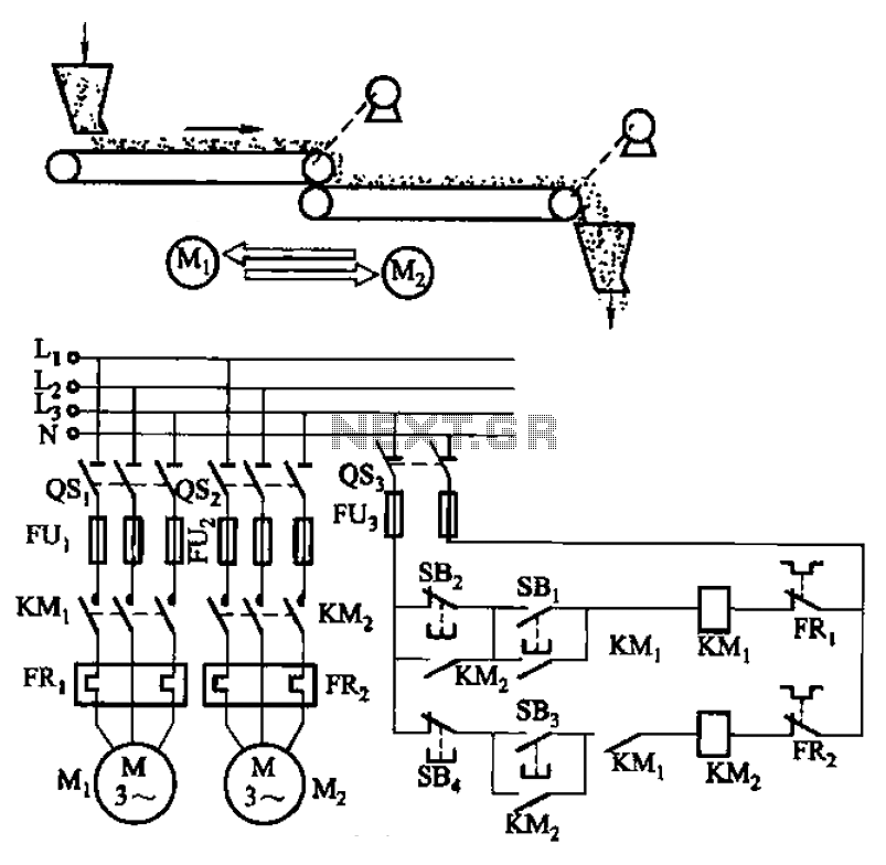
The circuit depicted in Figure 3-86 utilizes a line utilization time relay to control two motors, starting one before the other after an initial stall. The time relay KTi can be adjusted to modify the starting interval of the...