
DC motor 12V speed controller circuit with explanation

The described encoder circuit operates as a feedback control system for a DC motor, utilizing the HA-2542 operational amplifier to maintain the desired speed efficiently. The position encoder is critical in this setup, as it translates the motor's rotational position into electrical pulses. These pulses are characterized by a consistent width, allowing for precise timing and frequency measurement.
The capacitor CI serves as a charge storage element, integrating the pulses from the encoder to produce a smooth voltage signal that reflects the average speed of the motor. This voltage is then fed into the inverting input of the HA-2542. The non-inverting input is set to a reference voltage, which can be adjusted to represent the target speed of the motor. The operational amplifier compares these two signals, and any difference results in an output that adjusts the motor's drive signal accordingly. This feedback mechanism ensures that the motor operates at the desired speed, compensating for any variations due to load changes or other factors.
In terms of component selection, the HA-2542 is chosen for its high performance in terms of gain and bandwidth, making it suitable for real-time speed control applications. The circuit's simplicity is advantageous, as it minimizes the number of external components required, which can lead to reduced complexity and cost.
The limitations mentioned regarding the encoder wheel can be addressed by employing a pulley system. By attaching a pulley to the encoder wheel, it becomes possible to use the motor's output to drive another device, such as a conveyor belt or a fan. This versatility allows the circuit to be applied in various applications beyond just motor speed control, enhancing its utility in automated systems. The use of a belt to connect the motor to other devices provides a mechanical means to transfer motion and control speed, further expanding the functionality of the circuit.A very simple encoder circuit for a dc motor can be constructed using this circuit diagram. As you can see in the circuit diagram, the system shown consists of the HA-2542, a small 12-Vdc motor, and a position encoder. During operation, the encoder causes a series of ``constant-width" pulses to charge CI. The integrated pulses develop a referenc e voltage, which is propor £ional to motor speed and is applied to the inverting input of HA-2542, The noninverting input is held at a constant voltage, which represents the desired motor speed. A difference between these two inputs will send a corrected drive signal to the motor, which completes the speed control system loop.
As you can see the circuit requires few external components, but because of the encoder wheel it has a limitations of use. If you put a pulley under the encoder wheel you can command the speed of other device, by connecting the (motor and other device ) using a belt
🔗 External reference
Related Circuits
Instructions for constructing and utilizing a basic PIC programmer using readily available and inexpensive components. The total cost for building the programmer is under $1.50. The simple PIC programmer is designed to facilitate the programming of PIC microcontrollers, which are...
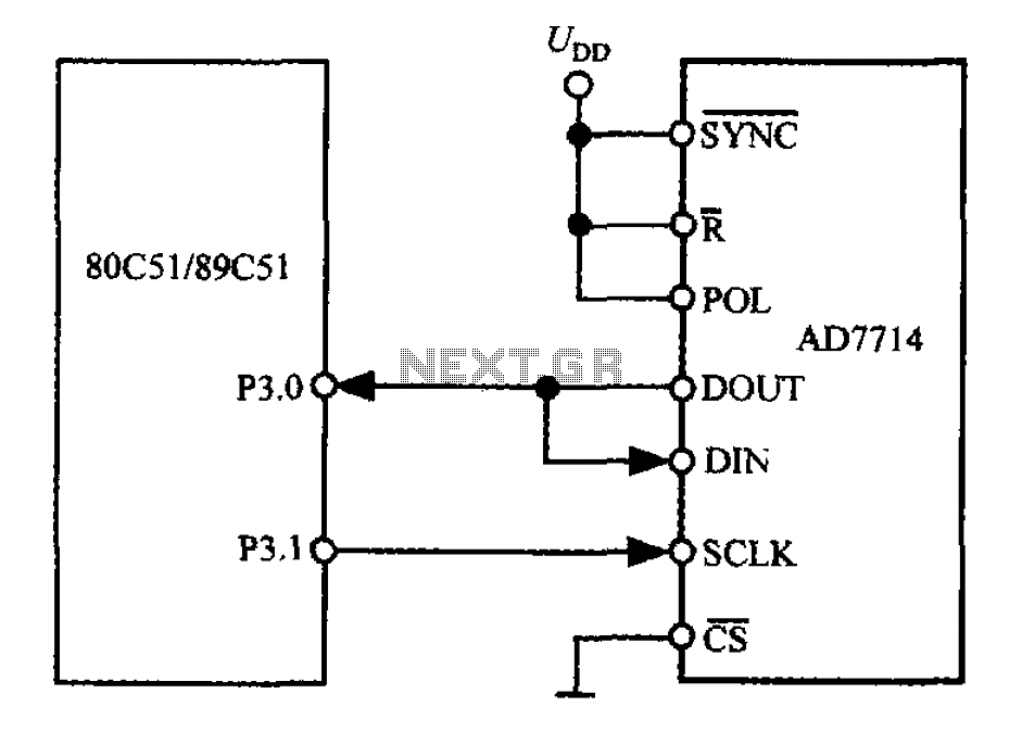
The 3-wire interface to the AD7714 can be utilized with various microcontrollers, including microcontrollers and microprocessors. This 3-wire serial interface is particularly suitable for isolation systems, allowing the use of optical couplers. The interface circuit between the AD7714 and...
The circuit incorporates components Q, C, and ZD, which are responsible for the bias and buffer stages. Its primary objective is to ensure stable MOSFET gate operation and provide an offset voltage through a voltage buffer amplifier stage with...

The transmitter is constructed on a Printed Circuit Board (PCB). This board incorporates track inductors for L1, L2, and part of L3. The section surrounding Q1 functions as the oscillator section, with the oscillation frequency determined by L1, C4,...
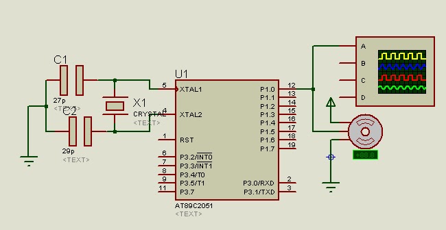
A program is available to control a simple servo motor in both directions. This program has been tested and can be shared for others to benefit from it. It allows the servo motor to rotate in both clockwise and...
CocaCola clearly stated that his circuit did not work correctly; the series was only complete when both LEDs were enabled, not otherwise. The circuit in question appears to involve a series configuration of light-emitting diodes (LEDs) that require both components...