
6 to 35kV substation cable entry into the segment of Lightning b

The 6-35kV cable line substation is designed to manage high-voltage electrical distribution while ensuring safety against lightning strikes. The lightning protection system is a critical component that safeguards the integrity of the electrical infrastructure. It involves the installation of surge arresters and grounding systems that divert excessive voltage away from sensitive equipment and structures.
In the case of single-core cables, particular attention must be paid to the termination of the metal sheath. This metal sheath serves as a protective barrier against electromagnetic interference and physical damage. The proper grounding of this sheath is essential to prevent potential electrical hazards. The ground clearance, denoted as JX, must comply with local regulations and standards to ensure adequate protection against lightning-induced surges.
The design of the substation should include a detailed schematic that outlines the placement of lightning rods, grounding electrodes, and surge protective devices. The schematic should also indicate the routing of cables, the connection points for grounding, and the specifications for the materials used in the construction of the lightning protection system. Proper implementation of these elements will enhance the reliability and safety of the substation, ensuring uninterrupted service in adverse weather conditions.6-35kV cable line substation, into its line of lightning protection can be Figure (a), the protection of access lines; for single-core cable, the end of the metal sheath shall be subject to the protection of ground clearance JX, as ( b). 6 to 35kV substation cable entry into the segment of Lightning b
Related Circuits
A multi wire cable tester with a separate LED for each wire. Will show open circuits, short circuits, reversals, earth faults, continuity and all with four IC`s. Designed initially for my intercom, but can be used with alarm wiring,...
The TX audio cable can be more complex than the RX audio cable. Typically, the TX audio cable requires a circuit to reduce the voltage from the sound card's LINE OUT jack; otherwise, the radio's transmit circuit may be...
To simplify the driver circuit, a multiplexer circuit can be utilized as a solution. With this multiplexed BCD decoder, only one BCD is required. A multiplexer (MUX) is an essential component in digital circuits, allowing multiple input signals to be...
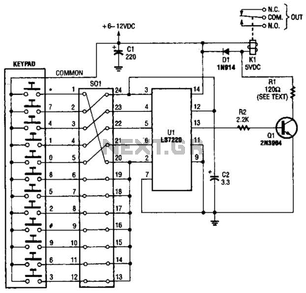
A block pinout diagram of the LS7220 keyless-lock IC is presented. The keypad must provide each key with a contact to a common connection. In this instance, the common connection is linked to the positive supply rail, allowing a...
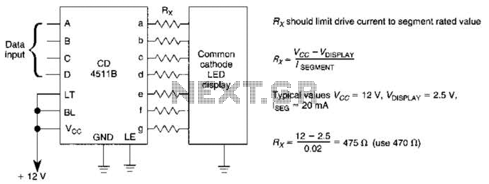
A CD4511B CMOS LED display driver can be utilized to operate a common cathode LED display. Current limiting resistors are employed to restrict the segment current to the specified value at the maximum supply voltage. The CD4511B is a...
This project aims to develop expertise in using seven-segment displays in various applications. The system will be designed to display any integer from 0 to 9999 using four seven-segment displays. A function named Print() will be created to facilitate...