
Transmit Audio Cable

Option 1: Instead of using two resistors, a 4.7K Ohm variable resistor (potentiometer) can be utilized to provide more control over attenuation, although it may be bulkier.
Option 2: An alternative schematic combines a potentiometer with a fixed resistor to create a more manageable range of settings.
The sound card connector will require a plug compatible with the sound card's LINE OUT jack, likely a 1/8" (3.5mm) stereo 3-conductor male mini-plug (e.g., Radio Shack part #274-284 - pkg. of 2). A mono plug should not be used. For pinout information regarding the radio, it is advisable to consult resources such as Buck's packet site, where specific pinout schematics can be found by selecting the appropriate cable for the radio model.
For mobile or base radios, either the microphone connection or, preferably, the radio's dedicated "data" jack should be used, which typically shares the same connector as the PTT and RX lines, unless the speaker jack is being utilized for RX audio. For handheld radios, the TX audio will connect to the radio's microphone jack, which usually requires a 3/32" (2.5mm) stereo or mono sub-mini plug. If the radio's user manual specifies the use of a stereo plug, it is essential to comply. Additionally, the PTT line will also be connected through this plug. Reference the radio's instruction manual or the aforementioned websites for detailed pinout information and any necessary resistors or capacitors for the PTT and TX lines.
For HF band usage, some radios may utilize different TX audio pins for HF and VHF/UHF operations, such as the ICOM 706. The user manual should provide the necessary pinout instructions. This differentiation may resolve issues where an interface transmits correctly for HF digital modes like PSK31 but fails to transmit audio on VHF/UHF, or vice versa.
Regarding 9600 baud operation, newer radios designed for 9600 baud may have a designated data jack pin for this transmission speed, though many models use the same pin for both 1200 and 9600 baud. However, radios typically include a menu option for "data speed," which adjusts the radio's input voltage sensitivity; this selection may amplify or attenuate the TX audio accordingly. For instance, the "9600" setting allows the pin to accept a full 2V maximum, while the "1200" setting limits it to approximately 40mV maximum.The TX audio cable can be a little more complicated then the RX audio cable. Normally, the TX audio cable must have a circuit to attenuate the voltage leaving the sound card`s LINE OUT jack, otherwise the radio`s transmit circuit will be overdriven. Note: Use the LINE OUT jack, do not use the SPEAKER jack (which is found on some older sound cards) . If your card or laptop only has a HEADPHONE jack, it can be used, but you will need to lower the sound card`s TX audio volume. Quality will usually not be quite as good as a LINE OUT. The exact attenuation will depend on both your radio and sound card. An approximation is a 100:1 attenuation (40 dB) which will reduce the sound card output level (max. 2 Volt p-p) down to the level your radio normally would expect for microphone ( 20 -40 milliVolt p-p ).
For example, a 50:1 attenuation works better for me, since I use my my radio`s data jack which has a maximum input voltage of 40 mV p-p. Don`t Overdrive Your Radio! If a sound card (or a TNC) overdrives a radio`s input circuit (i. e. it is too loud), the radio may distort the true packet tones as it tries to limit the signal to a maximum deviation of approx.
5 kHz. The attenuation circuit described on this page attempts to prevent such overdriving and distortion. Interestingly, a 1200 baud packet station that is properly adjusted with 3. 25 kHz of deviation (+/-. 25) should sound softer than channel noise! Option #1: Instead of the two resistors, you could use a 4K7 (4. 7K) Ohm variable resistor (potentiometer/pot). The pot would actually give you more control over the attenuation, although a pot is bulkier. Option #2 : Or here`s a schematic of a circuit that combines a pot with a fixed resistor to give the pot a less delicate range of settings and make is easier to adjust: Sound card connector: You will need a plug that will fit the sound card LINE OUT jack, probably a 1/8" (3. 5mm) stereo 3 conductor male mini-plug (e. g. Radio Shack part #274-284 - pkg. of 2). Do not use a mono plug 2 conductor plug. If you need your radio`s "pinout" information, you`ll probably find it at or Buck`s packet site (on Buck`s site, go to the page for TNC-to-radio cables and find your radio.
Click on the "Add to Cart" button for the cable for your radio and this will reveal a schematic of the radio`s pin out information. ) Mobiles or Base Radios: You can use either the microphone connection or preferably the radio`s special "data" jack, if it has one.
You`ll be using the same connector as the one used for yourPTT and RX line, unless you`re using the speaker jack for RX audio). Handhelds: TX audio will go to the radio Microphone jack, which usually require a 3/32" (2. 5mm) stereo (3 conductor) or mono (2 conductor) sub-mini plug. If your radio`s user manual says to use a stereo plug instead of a mono plug, be sure you do. You`ll also be feeding your PTT line into this plug. Check your radio`s instruction manual or either of the web sites mentioned above for pin-out information and any resistor and/or capacitor that may be required for the PTT and TX lines of your radio.
HF Band Use: Some radios may use different TX audio pins for HF and VHF/UHF. The ICOM 706 is one. Consult your radio`s user manual for pin out instructions. This can be the solution if your interface transmits correctly for HF digital modes such as PSK31 but won`t transmit audio on VHF/UHF, or vice versa 9600 baud use: The newer 9600-ready radios might have a data jack pin for "9600 baud transmit", although many have both 1200 and 9600 on the same pin. The radios will however most probably have a menu choice for "data speed" that affects the radio`s input voltage sensitivity, i.
e. the menu selection may amplify or attenuate the TX audio. (Check your radio`s user manual. ) For example, the "9600" choice allows the pin to accept full 2V maximum, where "1200" accepts only approximately 40mV maximum. That means, to get things ri 🔗 External reference
Related Circuits
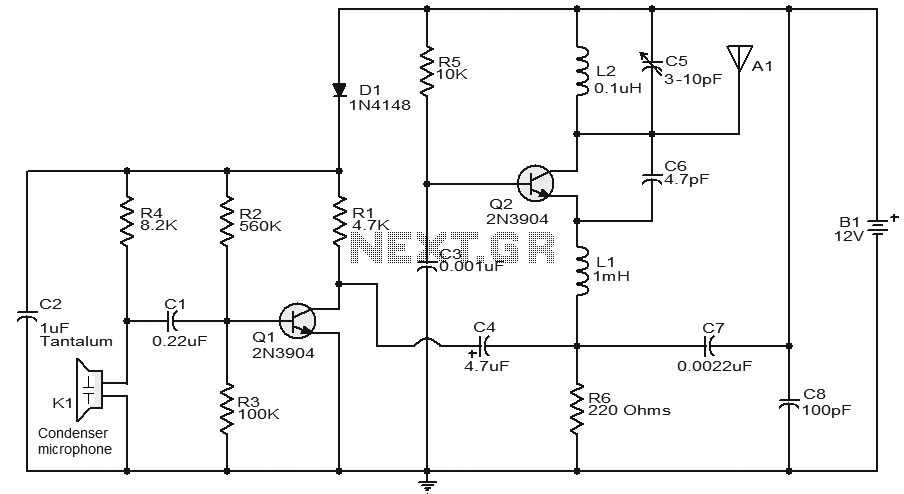
This circuit features a very stable and simple FM transmitter design. This transmitter can achieve a range of approximately 200 meters when properly matched. The FM transmitter circuit typically consists of several key components: an oscillator, modulator, amplifier, and antenna....
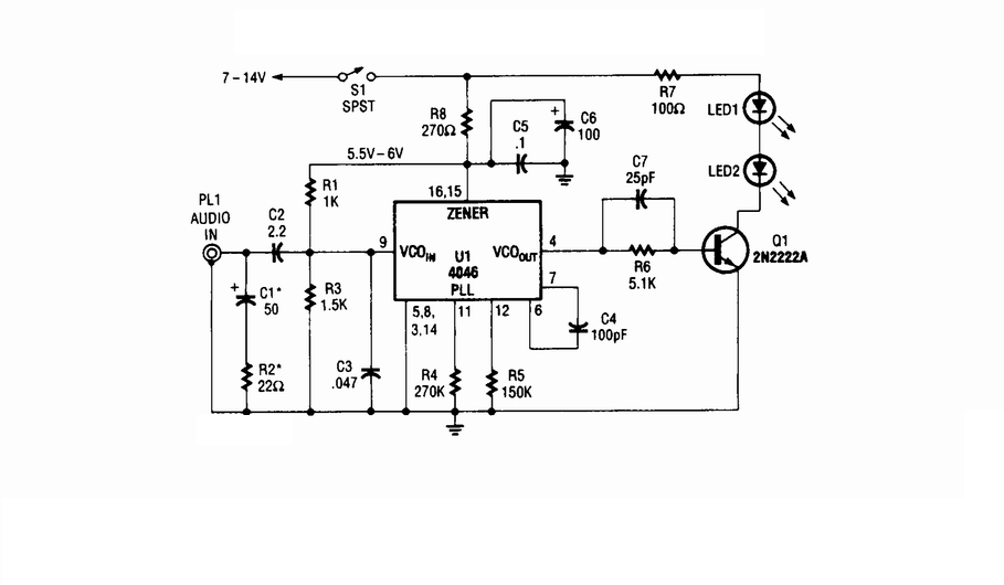
Wireless infrared headphone transmitter. Audio input from PL1 frequency modulates the voltage-controlled oscillator (VCO) section of a 4046 phase-locked loop (PLL) chip. The VCO output drives Q1, a switching transistor, which in turn drives two infrared (IR) LEDs. The wireless...
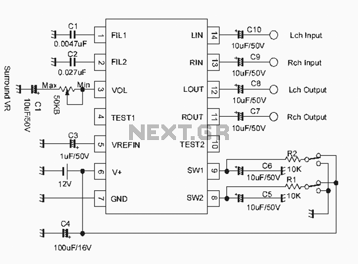
The NJM2701 3D surround sound audio processor integrated circuit can be designed into a very simple 3D surround sound system. The NJM2701 reproduces 3D surround sound using only two speakers and is suitable for various audio applications, including micro-components,...
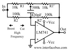
This discussion continues from the audio tone control topic, which introduced both passive and active tone controls. The follow-up topics may include a 2-Band Active Tone Control or a 3-Band Active Tone Control. An audio equalizer is utilized to...
The circuit of an FM Tracking Transmitter Circuit or Remote Control Transmitter Circuit is explained using a 555 IC and 2N4392 transistors. The FM Tracking Transmitter Circuit utilizes a 555 timer integrated circuit (IC) configured in astable mode to generate...
The Audio Automatic Gain Control (AGC) circuit monitors the output signal level of an audio preamplifier. When the input signal increases, the AGC circuit automatically reduces the amplifier's gain. Conversely, when the input signal decreases, the AGC circuit increases...