
Multiplexed BCD Decoder 7 Segments Driver

A multiplexer (MUX) is an essential component in digital circuits, allowing multiple input signals to be routed to a single output line. In the context of a BCD (Binary-Coded Decimal) decoder, the use of a multiplexer can significantly reduce the complexity of the driver circuit. The BCD decoder converts binary inputs into a decimal output, which is useful in applications requiring numerical displays or control systems.
In this design, a single BCD decoder can be employed in conjunction with the multiplexer to manage multiple BCD inputs efficiently. The multiplexer selects one of the several BCD inputs based on control signals, enabling the decoder to process only the active input at any given time. This configuration not only minimizes the number of components needed but also streamlines the overall circuit design.
The implementation involves connecting the outputs of the multiplexer to the input of the BCD decoder. Control lines determine which BCD input is active, allowing for dynamic selection of the input data. The output of the BCD decoder can then drive a display or other downstream components.
The benefits of this approach include reduced power consumption, lower component count, and simplified wiring, which can lead to enhanced reliability and ease of troubleshooting. Additionally, this configuration can be adapted to various applications, such as digital displays, counters, or any system requiring the conversion of binary data into a decimal format.
In summary, integrating a multiplexer with a BCD decoder provides an efficient solution for managing multiple binary inputs, thereby simplifying the design and operation of digital circuits.To save the complexity of driver circuit, a multiplexer icrcuit can be used for the solution. With this multiplexed BCD decoder, we can use only one BCD.. 🔗 External reference
Related Circuits
The SP6331, SP6333, and SP6335 are quad power supervisory circuits designed for microprocessor reset applications, featuring multiple reset voltage options. This family of devices offers low voltage monitoring capabilities for up to four supply voltages, with two precision factory-set...
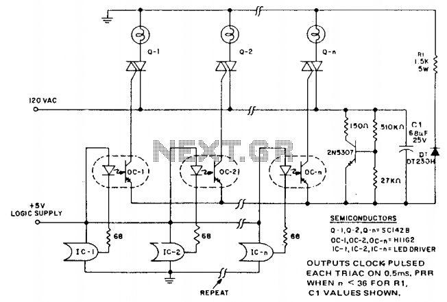
In microprocessor control of multiple loads, minimizing the cost per load is essential. A typical application is a large display that drives arrays of incandescent lamps. This circuit achieves minimal component cost per stage by utilizing optocoupler triggering of...
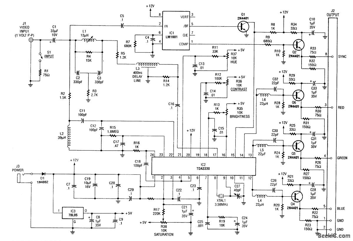
An NTSC/RGB decoder is presented, utilizing a TDA3330 to decompose a 1-V input video signal into its red, green, and blue components, as well as composite sync. The circuit includes an integrated sync separator (LM1881) designated as U1. This...
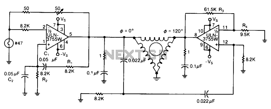
By varying either R1 or R2, the oscillator frequency can be adjusted over a narrow range. The R3/R4 ratio sets the second amplifier's gain to compensate for signal attenuation occurring in the phase shifters. The circuits can be driven...
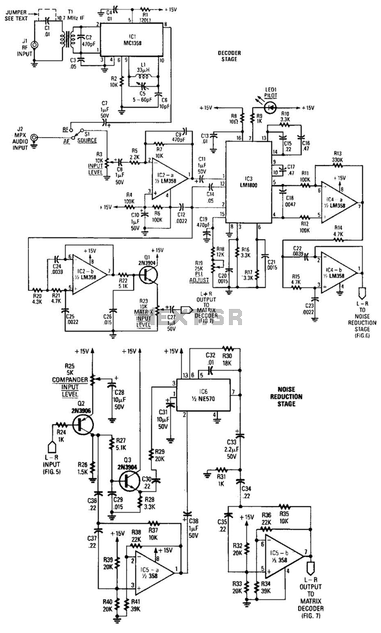
A block diagram of the stereo-TV decoder illustrates the overall relationships between the distinct sections of the circuit, while additional details of each subsection are provided. The decoder section is centered around TCI, a standard 4.5-MHz audio demodulator. The...
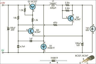
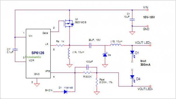
This circuit is designed to drive 1W LEDs that are commonly available. It addresses their non-linear voltage-to-current relationship and variations in forward voltage. The circuit utilizes a constant current driver configuration to ensure that the LEDs operate efficiently while maintaining...