
6 Transistor Tildens H-Bridge

The 6 transistor Tilden H-bridge circuit is a specific configuration used for driving DC motors, enabling control over the motor’s direction and speed. This circuit employs six bipolar junction transistors (BJTs) arranged in a bridge configuration, allowing for both forward and reverse motor operation. The transistors are typically arranged in pairs, with each pair controlling the current flow through the motor in opposite directions.
In this configuration, two transistors are turned on to allow current to flow in one direction, while the other two transistors are turned off. To reverse the direction of the motor, the opposite pair of transistors is activated. The use of BJTs in this circuit allows for efficient switching and control, making it suitable for various applications, including robotics and automation.
The circuit is often used in BEAM robotics, where simple, efficient motor control is essential. The Tilden H-bridge's design minimizes component count while maintaining functionality, making it an attractive choice for hobbyists and engineers alike. Bruce Robinson’s explanation of the circuit provides valuable insights into its operation, highlighting the importance of proper transistor selection and biasing to ensure reliable performance.
In summary, the 6 transistor Tilden H-bridge circuit is a versatile and foundational design in the realm of DC motor control, with applications extending into various fields of electronics and robotics. Its historical significance and practical utility continue to influence modern circuit design.This diagram is certainly the 6 transistor Tilden H-bridge circuit; while not as old as the original basic H-bridge, this goes way back, and will be the basis for a lot of BEAM driver circuits. Bruce Robinson explaination about this circuit.. 🔗 External reference
Related Circuits
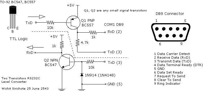
There are many who built the Easy Programmer or C-52 Evaluation Board, asking for the RS232C level converter chip, DS275. Many have changed to MAX232 instead, because it is not available in their home. Here is another simple and...

None of those devices is very suitable. The drivers aren't specified to operate with 3.3V gate signals, and although the typical graph shows that a... The devices referenced in the original input are not appropriate for the intended application due...

A flip-flop, functioning as an astable multivibrator, can be utilized to generate timing signals in music applications such as a metronome. This can be achieved by adjusting the transistor bias resistor with a value of 100k. The astable multivibrator configuration...

This is a component of a 100W RF amplifier. This circuit is constructed using the RF power transistor BLY94. Components include the BLY94 transistor, inductor, and others. The 100W RF amplifier circuit utilizing the BLY94 transistor is designed to amplify...

The circuit is designed around a 741 general-purpose operational amplifier (op amp) configured as a voltage follower, providing a voltage gain of one. The output from the 741 is utilized to drive a 50-meter movement. Potentiometer R7 is employed...

This series-feedback configuration of components provides a high input impedance and stable, wide-band gain video amplifier suitable for general-purpose applications. Below is the schematic representation of the circuit. The described video amplifier circuit employs a series-feedback topology, which is instrumental...