
60 watt bass amplifier

The guitar amplifier circuit is designed to provide high performance with a simplified approach. The straightforward circuitry is advantageous for both manufacturing and maintenance, making it accessible for both hobbyists and professionals. The built-in loudspeaker protection mechanism, facilitated by capacitor C8, is a critical feature that enhances the reliability of the amplifier by preventing potential damage to the loudspeakers during output transistor failures.
The preamplifier section, powered by the 60V rails, plays a vital role in amplifying the weak signals from the guitar. The two-transistor gain block is a common configuration that provides significant output voltage while maintaining high input overload capability, which is essential for handling dynamic guitar signals without distortion.
When selecting output transistors, the choice of MJ11014, MJ11013, TIP142, or TIP147 is significant. These transistors are capable of handling the power requirements without introducing excessive thermal stress. The thermal management of the output stage is critical; therefore, the placement of the sensing transistor (Q2) in close proximity to the output transistors ensures accurate thermal feedback for biasing, which is essential for maintaining performance and reliability.
The adjustment of resistor R9 is a key step in the calibration process. By setting R9 to achieve half the voltage supply across the positive lead of C7 and ground, the circuit can be optimized for performance. Utilizing an oscilloscope for this adjustment allows for precise monitoring of the output waveform, ensuring that the amplifier can achieve symmetrical clipping at maximum output power, which is crucial for maintaining audio fidelity during high-volume operation.
Overall, this guitar amplifier design exemplifies a balance between simplicity, performance, and reliability, making it suitable for various applications in music performance and recording.The advantages for a guitar amplifier are the very simple circuitry, even for comparatively high power outputs, and a certain built-in degree of loudspeaker protection, due to capacitor C8, preventing the voltage supply to be conveyed into loudspeakers in case of output transistors` failure. The preamp is powered by the same 60V rails as the power amplifier, allowing to implement a two-transistors gain-block capable of delivering about 20V RMS output. This provides a very high input overload capability. The Darlington transistor types listed could be too oversized for such a design. You can substitute them with MJ11014 (Q3) and MJ11013 (Q4) or TIP142 (Q3) and TIP147 (Q4). In all cases where Darlington transistors are used as the output devices it is essential that the sensing transistor (Q2) should be in as close thermal contact with the output transistors as possible.
Therefore a TO126-case transistor type was chosen for easy bolting on the heatsink, very close to the output pair. R9 must be trimmed in order to measure about half the voltage supply across the positive lead of C7 and ground.
A better setting can be done using an oscilloscope, in order to obtain a symmetrical clipping of the output wave form at maximum output power. 🔗 External reference
Related Circuits
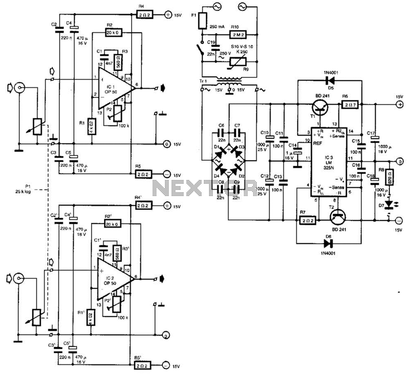
Built around Precision Monolithics Inc. OP-50 operational amplifiers, this amplifier is capable of driving 100- to 14-ohm headphones. It maintains a flat frequency response within 0.4 dB from 10 Hz to 20 kHz and exhibits a total harmonic distortion...
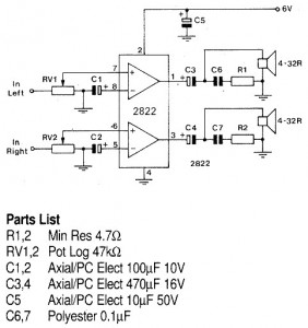
A 1W stereo headphone amplifier circuit, based on the TDA2822, is designed for portable players, radios, and other electronic devices that utilize headphones as the output. The TDA2822 is a dual audio power amplifier IC capable of delivering up to...
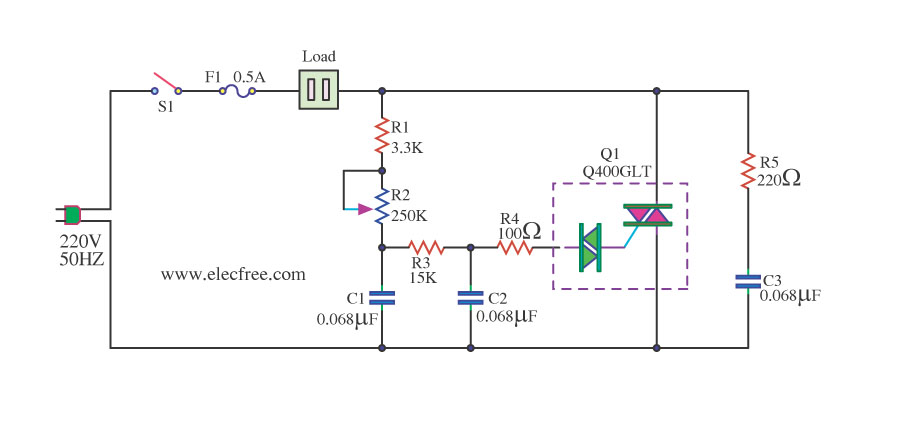
This is a 1200-watt AC power dimmer that utilizes a triac Q4006LT. The 1200-watt AC power dimmer circuit is designed to control the brightness of incandescent lamps and other resistive loads. The core component, the triac Q4006LT, is a semiconductor...
This amplifier circuit is designed to enhance TV signals in the UHF range. It employs a low-noise transistor, providing an amplification of 10 to 15 dB within the frequency spectrum of 400 MHz to 850 MHz. It is crucial...
This article is intended for individuals interested in constructing their own car amplifier. The fundamental calculations will be discussed below. Understanding these concepts will enable the construction of a car amplifier independently. The challenge in designing a car power...
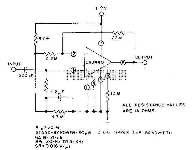
This circuit utilizes the low power leakage, high input impedance, frequency response, and capacitance characteristics of the CA3440 operational amplifier. Only one input coupling capacitor of 500 pF is required to attain a -3 dB low frequency response at...