
High input impedance amplifier CA3440

The described circuit leverages the unique properties of the CA3440 operational amplifier, which is known for its low power consumption and high input impedance. These features make it particularly suitable for applications that require minimal signal loading and high sensitivity. The circuit configuration involves a single input coupling capacitor of 500 pF, which plays a crucial role in setting the low frequency response of the system.
The choice of a 500 pF capacitor allows the circuit to achieve a -3 dB cutoff frequency at 20 Hz. This is essential for applications that necessitate the filtering of low-frequency signals while maintaining the integrity of higher frequency components. The -3 dB point indicates the frequency at which the output signal power drops to half of its maximum value, a critical parameter in audio and signal processing applications.
In practical terms, the CA3440's high input impedance ensures that the circuit does not significantly load the source signal, preserving the original waveform characteristics. The low power operation of the CA3440 is advantageous for battery-powered or energy-efficient designs, making this circuit ideal for portable devices or applications where power conservation is a priority.
Overall, the circuit design is optimized for low-frequency performance while taking full advantage of the CA3440's capabilities, providing a robust solution for various electronic applications requiring high fidelity and low power operation.This circuit takes advantage of the leakage of low power, high input impedance, frequency and capacity of the excellent CA3440.
Only one input coupling capacitor of 500 pF is needed to achieve a 20 Hz, -3 dB low frequency response.
Related Circuits
The amplifier circuit utilizes negative current feedback, which ensures that the load current is primarily influenced by the input signal rather than the loudspeaker's impedance. The inductor current from the loudspeaker generates a voltage across resistor R7, which is...
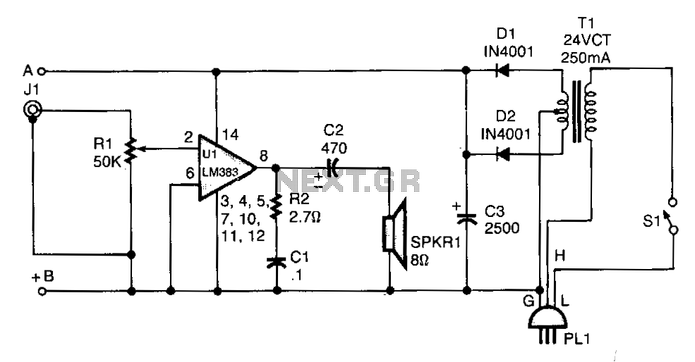
T1 isolates the unit from the line and has a 24-V, center-tapped secondary. The output of the transformer is rectified by diodes D1 and D2 and filtered by capacitor C3 to provide 15 to 18 Vdc. The LM383 has...
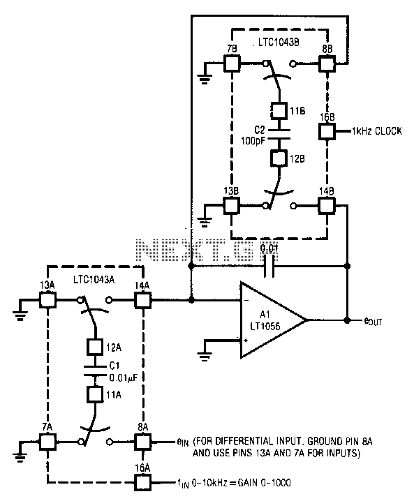
The circuit utilizes the LTC1043 in a variable gain amplifier configuration, which offers continuously adjustable gain, gain stability of 20 ppm/°C, and supports both single-ended and differential inputs. Two separate LTC1043 devices are employed in the design. The LTC1043B...
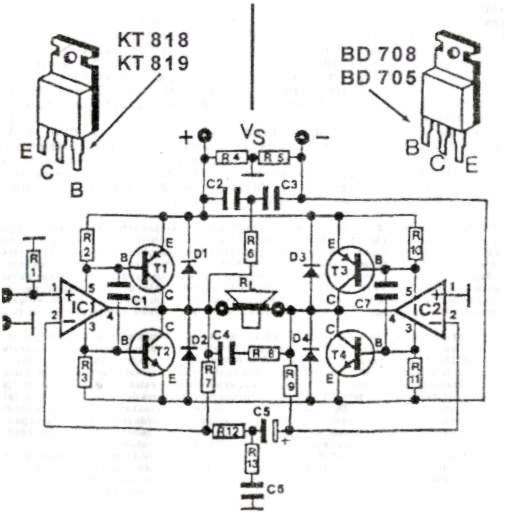
This audio amplifier circuit provides up to 200 W of high-quality output for loudspeakers with impedances ranging from 4 to 16 ohms. The operating voltage is between 24 and 36 V, with a maximum current of 5 A. The audio...
Simple electronics provides the foundation for many closed loop control systems. Since the principle components that we would wish to control for HSP are electronic in nature, an electronic control system is the natural choice. As this document is...
This circuit is very basic to build and puts out great power for your car or home. Keep all leads as short as possible. The described circuit is a fundamental power amplifier, suitable for applications in automotive or residential settings....