
60 watt switching power supply

The 60 Watt Switching Power Supply is designed to convert an input voltage to a regulated output voltage while maintaining high efficiency and compact size. This power supply typically employs a switching regulator topology, which utilizes high-frequency switching elements to minimize energy loss during the conversion process.
The circuit generally consists of several key components: a transformer, switching transistors, diodes, capacitors, and control circuitry. The transformer is crucial for voltage step-down and isolation, while the switching transistors, often MOSFETs, are responsible for rapidly turning on and off to control the energy transfer to the transformer.
Diodes are used for rectification, converting the AC output from the transformer back to DC. Capacitors smooth the output voltage, reducing ripple and ensuring a stable supply. The control circuitry monitors the output voltage and adjusts the duty cycle of the switching transistors to maintain the desired output level under varying load conditions.
The efficiency of a switching power supply can be significantly higher than that of linear power supplies, often exceeding 85%, making them suitable for applications where thermal management and size constraints are critical. This type of power supply is widely used in various electronic devices, including computers, telecommunications equipment, and industrial applications.
Understanding the schematic diagram associated with this power supply is essential for troubleshooting and design enhancement, as it provides insights into the interconnections and operational principles of the components involved.60 Watt Switching Power Supply power supply. Go to that page to read the explanation about above power supply related circuit diagram. 🔗 External reference
Related Circuits
This regulated power supply was built as a simplified outboard version of a PSU in my first phono stage. Replacing hexfreds with tube rectifier eliminates the need for power-on sequencing. Chassis (salvaged from a hospital laser PSU) size is...
4 simple 12Vdc power supply circuits with output voltages around 12V. First power supply circuit is built with BD139, one zener diode and a few passive components. Each of the schematic is very simple to construct and will function...
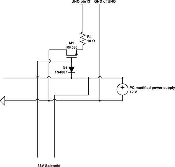
A 9 V DC battery initially powered the solenoid valve effectively. However, the solenoid did not generate sufficient force due to inadequate DC power. A modification was made to use a computer power supply as the power source. Providing...
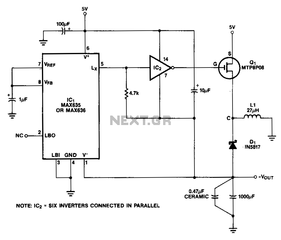
In this circuit, a CMOS inverter, such as the CD4069, is utilized to convert the open-drain Lx output into a signal that is appropriate for driving the gate of an external P-channel MOSFET. The MTP8P03 has a gate threshold...
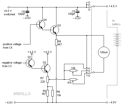
This project, based on an article published in the February 2008 edition of Radcom (the magazine of the Radio Society of Great Britain), describes a meter with a 50-ohm input impedance designed for measuring very small RF powers. Many...
A simple 9 Volt, 2 amp power supply utilizing a single integrated circuit (IC) regulator. This circuit is straightforward, as the regulator handles the majority of the work. The component used is the 7809 voltage regulator. The circuit consists primarily...