
9 Volt 2 Ampere DC Power SupplyCircuit

The circuit consists primarily of the 7809 voltage regulator, which is designed to provide a stable 9V output from a higher input voltage. The 7809 is a linear voltage regulator that can supply up to 1A of current, but it can be configured with additional components to handle up to 2A, depending on the heat dissipation and thermal management employed.
To construct the power supply, the input voltage, typically ranging from 12V to 35V, is fed into the input pin of the 7809. It is essential to ensure that the input voltage does not exceed the maximum rating of the regulator to prevent damage. The output pin delivers the regulated 9V, while the ground pin is connected to the circuit's common ground.
To enhance stability and performance, it is advisable to include input and output capacitors. A 0.33µF ceramic capacitor is recommended at the input to filter out high-frequency noise, and a 0.1µF ceramic capacitor at the output to improve transient response. Additionally, a larger electrolytic capacitor (typically 10µF to 100µF) can be placed at the output to provide further stability and handle load variations.
Thermal management is crucial when operating at higher currents. The 7809 regulator will dissipate heat proportional to the voltage drop across it and the current flowing through it. For instance, if the input is 12V and the output is 9V with a load drawing 2A, the power dissipation will be (12V - 9V) * 2A = 6W. A suitable heat sink should be attached to the regulator to prevent overheating and ensure reliable operation.
In summary, this simple 9V, 2A power supply circuit effectively utilizes the 7809 voltage regulator, complemented by appropriate capacitors for stability and a heat sink for thermal management, making it a reliable solution for various electronic applications.A simple 9 Volt 2 amp supply using a single IC regulator. There is little to be said about this circuit. All the work is done by the regulator. The 7809 c.. 🔗 External reference
Related Circuits
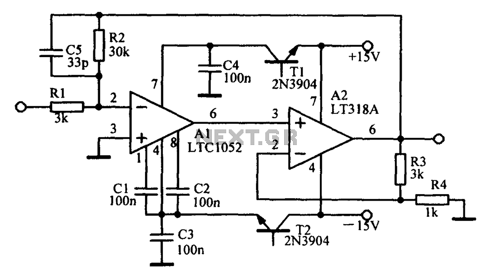
Amplifying circuit diagram to enhance the output current and voltage. An amplifying circuit is designed to increase the amplitude of an input signal, resulting in a higher output current and voltage. This type of circuit is commonly utilized in various...
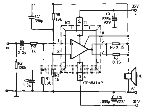
The Burr-Brown OPA541 chip is a power amplifier capable of operating with a maximum power supply voltage of 40V, delivering a continuous output current of up to 5A. The output current can be adjusted using an external resistor to...
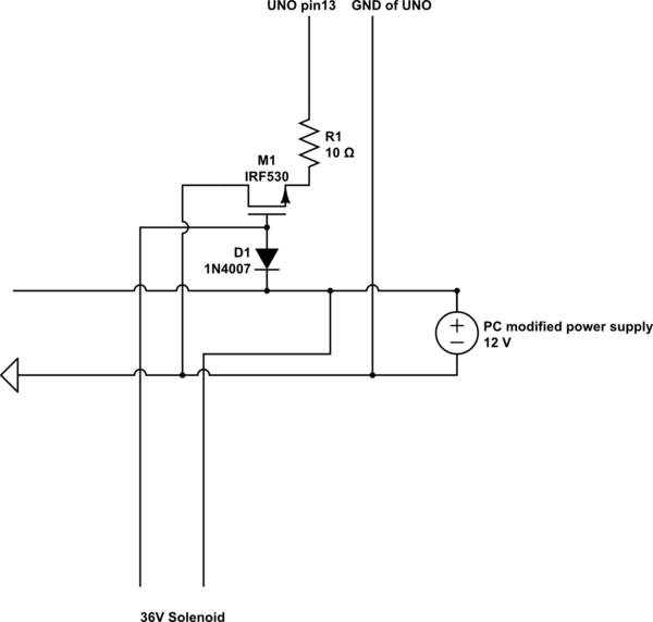
A 9 V DC battery initially powered the solenoid valve effectively. However, the solenoid did not generate sufficient force due to inadequate DC power. A modification was made to use a computer power supply as the power source. Providing...
Most devices used in amplifier output stages exhibit significant non-linearity, with transistors (both bipolar and FET) being particularly problematic. These components are almost always employed within a global feedback loop to mitigate their non-linear characteristics. Similarly, tetrode and pentode...
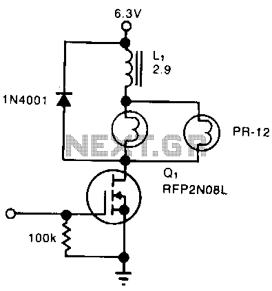
A simple solenoid driver utilizes incandescent lamp filaments as on-indicators to limit power consumption. High magnetic reluctance in the coil of an armature-driven device, such as a solenoid or relay, requires a surge of activation current, followed by a...
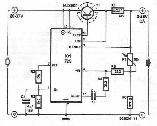
A simple variable power supply circuit can be designed using the LM723 regulator, which provides a maximum current of up to 2A and a variable voltage range between 2 and 25 volts. The LM723 voltage regulator is an integrated circuit...