
600 VOLTS POWER SUPPLY FOR QRO

The circuit described is a full-wave voltage doubler designed for amateur radio transmitters utilizing vacuum tubes, specifically the 807 or 1625 models. These tubes typically operate efficiently with a plate voltage ranging from 600V to 700V. The voltage doubler circuit is crucial for achieving the necessary high voltage from a lower voltage AC source, effectively doubling the input voltage, which, in this case, is approximately 230V AC. The output voltage, therefore, is expected to reach about 600V, suitable for the operation of the specified vacuum tubes.
In this circuit, Resistor R1 serves a critical role by limiting the initial surge of high voltage and current when the circuit is powered on. This protective measure is essential for preventing damage to the components and ensuring stable operation. The capacitors C1, C2, and C3, along with inductors L1 and L2, constitute the input line filter. This filter is designed to smooth the input waveform and reduce ripple, thereby providing a cleaner DC output.
Capacitors C4 and C5 are strategically placed to protect the diodes from high voltage transients that may occur on the AC line. These capacitors also play a vital role in minimizing inter-carrier hum modulation, which can adversely affect the radio frequency (RF) signals and overall performance of the transmitter. The combination of these components ensures that the circuit operates reliably while maintaining the integrity of the transmitted signals.
In summary, the described voltage doubler circuit is an essential component for amateur radio transmitters, providing the necessary high voltage while incorporating protective and filtering elements to enhance performance and reliability.Amateur Radio Transmitters using valves such as 807 or1625 works well with a plate voltage between 600V to 700 Volts.The circuit described here is a full wave voltage doubler. The output voltage is twice the input voltage. For 230V AC input the output will be nearly 600 Volts. Resister R1 is used to limit the initial high voltage and high currents. Capacitor C1, C2, C3 together with coils L1 and L2 form input line filter. The capacitors C4 and C5 protects diodes from high voltage transients on the AC line as well as reduces inter carrier hum modulation of the R.F picked up by the mains.
🔗 External reference
Related Circuits
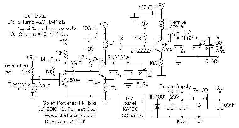
Here are some utility circuits for use with the Ramsey FM10a, and other small FM stereo transmitter kits. This information may be helpful for setting up a micro powered FM radio station. The FM10a and similar kits tend to...
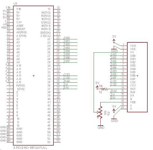
Displays are always beneficial. Until now, only 7-segment displays have been demonstrated for showing numbers using minimal resources. However, for displaying text or images, a simple LCD screen is required. There are basic LED screens available that operate on...
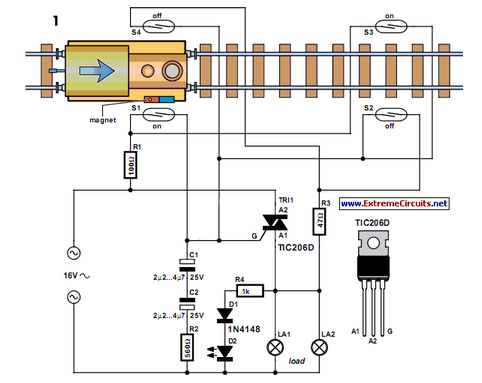
Modern electronics is essential for every large model railroad system, providing solutions to nearly every issue. Although ready-made products are available... Modern model railroad systems rely heavily on advanced electronics to enhance functionality and user experience. These systems often incorporate...
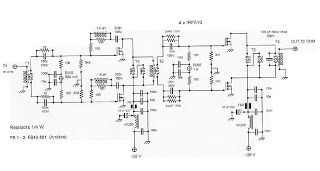
This is an RF Power Amplifier designed for low-cost QRP applications. The circuit operates over a broadband frequency range of 1.8 to 30 MHz, eliminating the need for tuning. The only adjustment required is to set the quiescent current...
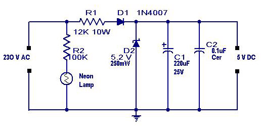
A simple transformerless power supply circuit with a diagram and schematics that provides a 5 volts DC output. This is a low-cost, low-current power supply circuit suitable for simple applications such as powering an LED. The transformerless power supply circuit...
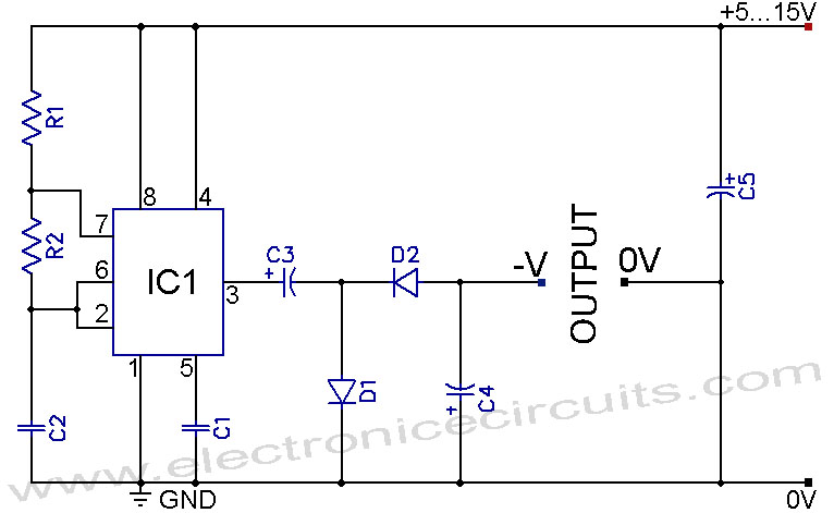
A 555 negative voltage power supply circuit can be created using a charge-pump configuration that incorporates a 555 timer, diodes, and additional components. The 555 timer is a versatile integrated circuit commonly used in various applications, including oscillators, timers, and...