
60W audio amplifier (2N3055)
")
The described circuit is a 60W class B power amplifier designed for audio applications. The power supply voltage range of 30V to 60V allows for flexibility in component selection and system integration. The optimal operating point is at 50V, which is crucial for achieving the desired output power while maintaining efficiency.
The input stage of the amplifier accepts a maximum input voltage of 0.8V to 1V, indicating that it is tailored for line-level audio signals. The design accommodates a variety of NPN transistors for the output stage, excluding Darlington pairs due to their higher saturation voltage which can affect performance in this application.
Capacitors C1 and C2 play a significant role in audio frequency response. C1 is responsible for coupling low-frequency signals, enhancing bass response as its capacitance value increases. Conversely, C2 manages high-frequency signals, where an increase in capacitance results in attenuation of treble frequencies. This frequency management allows users to tailor the amplifier's sound characteristics to their preferences.
The inclusion of a 500 Ohm trimmer resistor for biasing the output transistors is a critical feature. In class B amplifiers, a small bias current must flow through the output transistors to minimize crossover distortion. Adjusting this trimmer allows for optimization of sound quality at the expense of thermal performance, as higher bias currents lead to increased heat dissipation in the transistors. Conversely, reducing the bias current decreases heat generation but can negatively impact audio fidelity.
Overall, this power amplifier design is characterized by its adaptability, allowing for the use of readily available components while providing essential features for audio signal processing and quality enhancement. The design principles employed ensure that users can achieve satisfactory performance across a range of operating conditions.This is a simple and low cost 60W power amplifier. The optimal supply voltage is around 50V, but this amp can work from 30 to 60V. The maximum input voltage is around 0.8 - 1V. As you can see, in this design the components have a big tolerance, so you can build it with almost any components that you can find at home. The output power transistors can be any NPN types, but do not use Darlington types. Capacitor C1 regulates the low frequencies (bass), as the capacitance grows, the low frequencies are getting louder.
Capacitor C2 regulates the higher frequencies (treble), as the capacitance grows, the higher frequencies are getting quieter. This is a class B amplifier, this means, that a current must flow through the end transistors, even if there is no signal on the input. This current can be regulated with the 500 Ohm trimmer resistor. As this current increases, the sound of the amplifier is better, but output transistors are dispatching more heat.
If the current is decreased, the transistors are dispatching less heat, but the sound quality is decreased. 🔗 External reference
Related Circuits
Feedback - This is where part of the output signal is fedback to the input BUT 180° out-of-phase (i.e. partially cancels the input). If it were in-phase feedback then we would have an oscillator - which in this case...
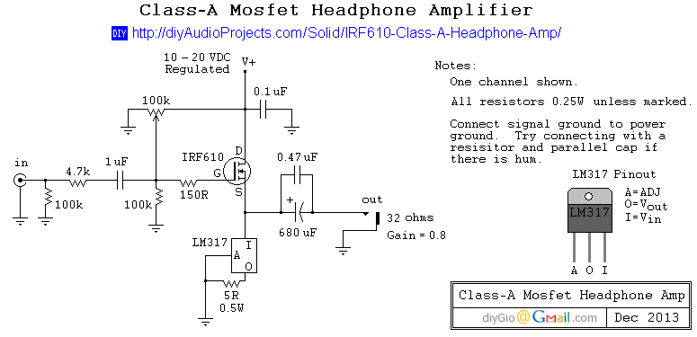
This is a simple and low-cost desktop headphone amplifier designed for office use. The amplifier concept is straightforward and adheres to a typical single-ended Class A circuit. The desktop headphone amplifier utilizes a single-ended Class A design, which is known...
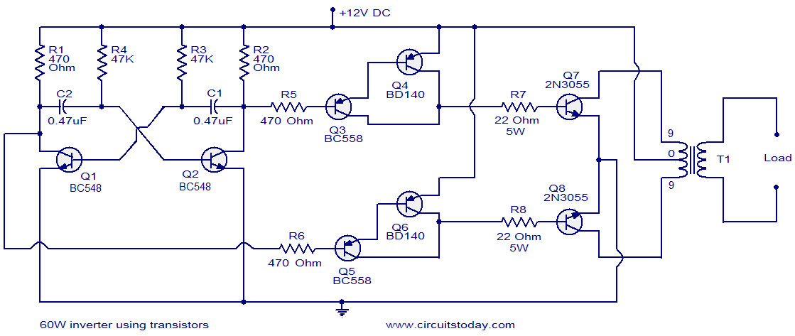
This circuit diagram illustrates a fully transistorized inverter capable of driving loads of up to 60W. Transistors Q1 and Q2 create a 50Hz astable multivibrator. The output from the collector of Q2 connects to the input of a Darlington...
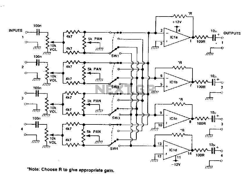
This circuit functions as a mixer for stereo tracks, utilizing a quad operational amplifier IC to provide gain for each track. The pan control allows for panning between two tracks when the switch is set to high, and when...
R1 2.2K 1/4W Resistor, R2 27K 1/4W Resistor, R3, R4 2.2K 1/2W Trimmers (Cermet or Carbon), R5 100R 1/4W Resistor, R6 1K 1/4W Resistor, R7, R8 330R 1/4W Resistors, C1 22 µF 25V Electrolytic Capacitor, C2 47pF 63V Polystyrene...
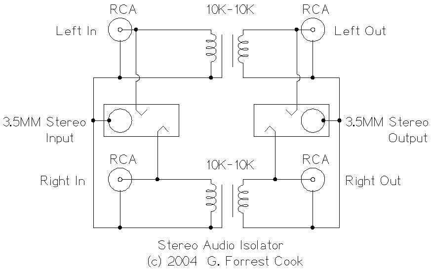
This circuit is useful for removing ground loop hum on a remote line level audio signal line. It can be used to connect a computer sound card to a stereo amplifier's line input. Other uses include tapping into a...