
60W Guitar Amplifier

The described circuit topology is a classic design for a guitar amplifier, leveraging the advantages of a single-rail power supply for simplicity and reliability. The use of capacitor coupling allows for effective isolation between the amplifier stage and the loudspeaker, which is essential for protecting the speaker from potential damage during fault conditions.
The preamplifier section, which operates from the same 60V rail, plays a crucial role in the overall performance of the amplifier by providing sufficient gain while maintaining a high input overload capability. This feature is particularly important for guitar amplifiers, where signal dynamics can fluctuate significantly.
The choice of output transistors is critical. While the original design suggests using Darlington pairs, which are known for their high current gain, alternative transistors such as MJ11014 and MJ11013 or TIP142 and TIP147 provide sufficient performance without the potential drawbacks of over-specification. The use of Schottky-barrier diodes for D1 and D2 is advantageous due to their fast switching characteristics, but the softer 1N4148 diodes offer a different tonal quality that may be desirable depending on the application.
Thermal management is a vital aspect of this design. The placement of the sensing transistor (Q2) in close proximity to the output transistors ensures accurate temperature sensing and protection, which is essential for maintaining performance and reliability during operation. The selected TO-126 case allows for effective heat dissipation, which is crucial for the longevity of the output devices.
Finally, the adjustment of resistor R9 is a necessary step in the calibration process, ensuring that the amplifier operates within its optimal parameters. Using an oscilloscope to achieve symmetrical clipping at maximum output power is an effective method for fine-tuning the amplifier's performance, allowing for a balance between power and fidelity that is essential for high-quality audio reproduction in guitar amplifiers.This design adopts a well established circuit topology for the power amplifier, using a single-rail supply of about 60V and capacitor-coupling for the speaker(s). The advantages for a guitar amplifier are the very simple circuitry, even for comparatively high power outputs, and a certain built-in degree of loudspeaker protection, due to capacitor
C8, preventing the voltage supply to be conveyed into loudspeakers in case of output transistors` failure. The preamp is powered by the same 60V rails as the power amplifier, allowing to implement a two-transistors gain-block capable of delivering about 20V RMS output.
This provides a very high input overload capability. The Darlington transistor types listed could be too over sized for such a design. You can substitute them with MJ11014 (Q3) and MJ11013 (Q4) or TIP142 (Q3) and TIP147 (Q4). D1 and D2 can be any Schottky-barrier diode types. With these devices, the harmonic modifier operation will be hard. Using for D1 and D2 two common 1N4148 silicon diodes, the harmonic modifier operation will be softer. In all cases where Darlington transistors are used as the output devices it is essential that the sensing transistor (Q2) should be in as close thermal contact with the output transistors as possible.
Therefore a TO126-case transistor type was chosen for easy bolting on the heatsink, very close to the output pair. R9 must be trimmed in order to measure about half the voltage supply from the positive lead of C7 and ground.
A better setting can be done using an oscilloscope, in order to obtain a symmetrical clipping of the output waveform at maximum output power. 🔗 External reference
Related Circuits
This is a 7-tube, 20-watt amplifier that must be used in conjunction with a preamplifier featuring volume and tone controls. A suitable recommendation is a 6-tube preamplifier. This amplifier utilizes 6BQ5 output tubes and employs a 5U4-G rectifier to...
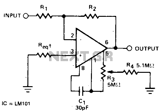
The required resistance (Req) may be zero or equal to the parallel combination of resistors R1 and R2 to achieve minimum offset. The circuit configuration described involves the use of two resistors, R1 and R2, connected in parallel. In a...
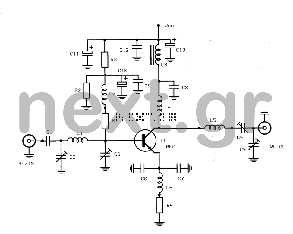
This structure is a radio frequency (RF) amplifier designed for small UHF TV transmitters, operating within the UHF channel range of 450-800 MHz. The amplifier enhances video signals in this frequency range and operates in Class A, utilizing the...
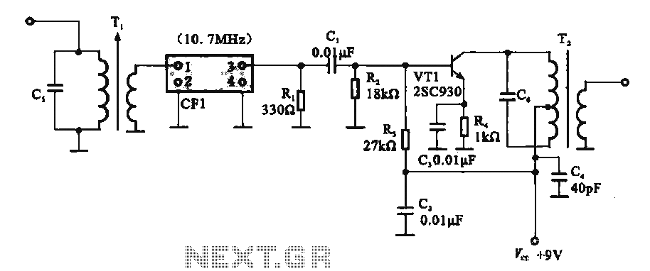
This circuit features a ceramic filter integrated with an FM intermediate frequency (IF) amplifier. The FM IF amplifier circuit primarily consists of an input variable voltage regulator (T), ceramic filters (CF1), and additional components such as the IF amplifier...
A combination of a common-source grounded base amplifier formed by cascaded amplifiers. The source is grounded, and a common base amplifier is combined into a cascaded amplifier. The graph below shows the low noise characteristics of the FET common-base...

A very high-power amplifier with 10 pairs of power transistors. It can utilize MJ15024 and MJ15025 or MJ21193 and MJ21194. These 20 transistors function as the final active components. The design is based on four integrated circuits: TL072, TL074,...