
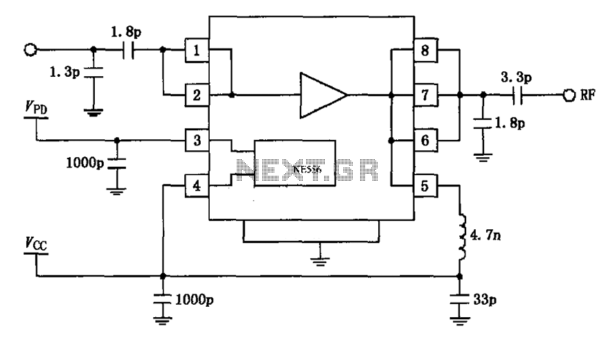
A combination of common-source grounded base amplifier formed by cascaded amplifier

The described circuit configuration consists of a cascaded amplifier system that integrates a common-source amplifier with a common-base amplifier. The common-source amplifier provides high voltage gain and is characterized by its input impedance, which is typically high. This makes it suitable for interfacing with various signal sources. The grounded source configuration ensures stability and minimizes distortion, making it ideal for low-noise applications.
The common-base amplifier, on the other hand, is known for its low input impedance and high output impedance. This configuration is particularly effective for high-frequency applications, as it provides a wide bandwidth and is less susceptible to the Miller effect, which can limit bandwidth in other amplifier configurations. The cascading of these two amplifier types allows for the benefits of each to be utilized, creating a hybrid amplifier that is capable of amplifying weak signals while maintaining low noise levels.
In practical applications, such as adaptive end units, this cascaded amplifier configuration serves as a preamplifier. It is designed to enhance the signal level before further processing, ensuring that the subsequent stages of the system can operate effectively with a strong, low-noise signal. The low noise characteristics of the FET (Field Effect Transistor) used in the common-base stage are crucial for maintaining signal integrity, especially in high-frequency environments.
Overall, the combination of a grounded source common-source amplifier and a common-base amplifier in a cascaded configuration results in a versatile and efficient low-noise preamplifier suitable for a variety of applications, particularly in telecommunications and signal processing.A combination of common-source grounded base amplifier formed by cascaded amplifier The source is grounded and common base amplifier combined into a cascaded amplifier. The gra ph below shows the low noise of the FET, common- base amplifier for amplifying the high frequency adaptive end units produced cascaded amplifier, often as a wideband low noise preamplifier amplifier.
Related Circuits
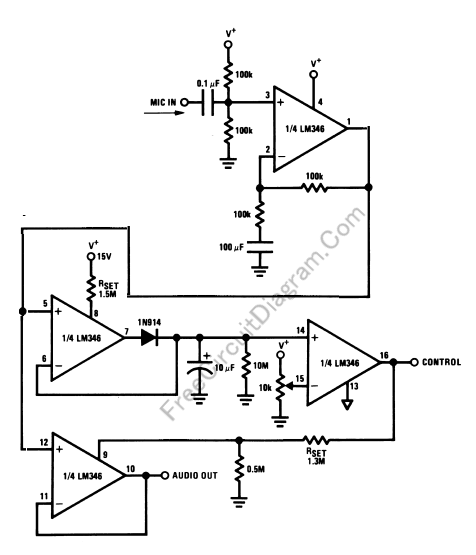
Feedback in a public address amplifier should be avoided. The ideal solution is to adjust the positions of the microphone and speaker; however, this is not always feasible in many situations. A frequency shifter that alters the output frequency...
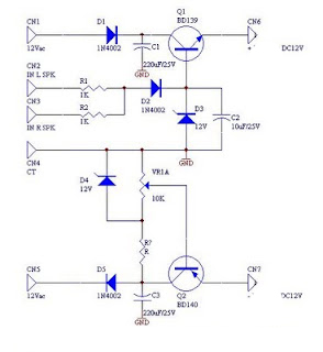
DC fan control circuit for a power amplifier. It features a variable speed DC fan that operates based on the input signal. The speed of the fan's rotation is dependent on the amplitude of the input signal received from...

The following circuit illustrates a practical electronics astable circuit diagram based on the 555 Timer IC. This circuit produces a pulse frequency of approximately 2Hz with a very low mark-space ratio, making it suitable for various applications. The single...
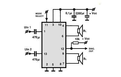
A simple Class B power amplifier can be constructed using the TDA8560 audio integrated circuit (IC). The TDA8560 amplifier features an internally fixed voltage gain, ensuring excellent channel balance. This audio amplifier project is capable of delivering dual 40-watt...
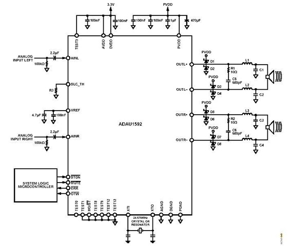
This is a stereo circuit schematic of the ADAU1592, a 2-channel, bridge-tied load (BTL) switching audio power amplifier. The ADAU1592 can be utilized in compact television sets, PC audio systems, and mini-component applications. According to the ADAU1592 datasheet, an...
The circuit depicted in the figure is based on the RF2126, a 2450 MHz end-stage linear power amplifier. The radio frequency (RF) signal enters through input pin 1 and is subsequently amplified by the amplifier stages (pins 5, 6,...