
Colorful Countdown Clock for tight timeline management using Arduino
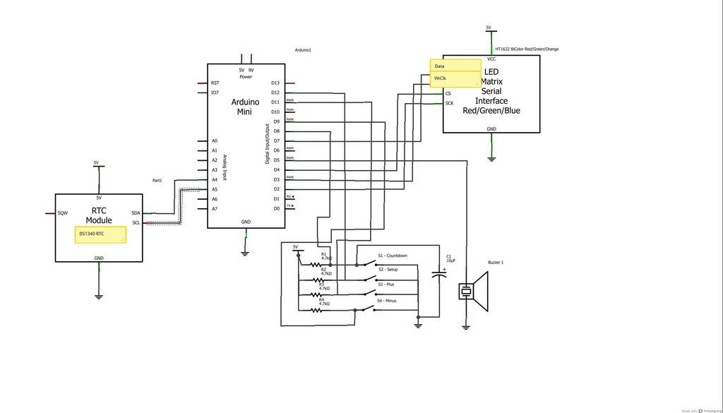
The schematic design for this project incorporates an Arduino Nano as the central processing unit, which interfaces with an LED matrix display and a real-time clock (RTC) module. The LED matrix serves as the visual output for displaying countdown timers and other relevant information during meetings. The RTC module, which can be a DS1307 or similar, maintains accurate timekeeping and allows for countdown functionality.
Connections for the LED matrix are made using six jumper wires, which should be routed from the Arduino's digital output pins to the corresponding input pins on the matrix. The RTC module requires four jumper wires for I2C communication, typically connecting to the SDA and SCL pins on the Arduino. It is crucial to ensure that all connections are secure to prevent any intermittent failures during operation.
Buttons for user interaction, such as setup, start/stop, and increment/decrement, should be connected to designated digital input pins on the Arduino. These buttons will allow users to modify the countdown timer settings and control the start and stop functions. A pull-down resistor configuration may be employed to avoid floating inputs when the buttons are not pressed.
The countdown timer's visual feedback is managed through the LED matrix, with color-coded indicators reflecting the time remaining. The Arduino's programming logic will handle the countdown process, changing the display color from green to yellow and finally to red as the timer approaches completion. An audible buzzer can be integrated to signal the end of the countdown, providing an additional alert mechanism.
For the temperature sensing aspect, the DS1820 sensor should be connected to a dedicated analog or digital pin on the Arduino, with appropriate pull-up resistors if necessary. The placement of the sensor is critical; it should be positioned away from the LED matrix to prevent heat from affecting temperature readings.
Overall, this project combines various components to create an effective time management tool for meetings, with a focus on user-friendly interaction and clear visual feedback. Proper assembly and programming are essential for ensuring reliable operation and functionality in real-world applications.Well, I have few good uses for it, one of them is ensure in meetings people are respectful of time and are not taking all the time for their own topics. Good for ship-room or SCRUM meetings. Following is a list of parts and for the special ones a link for where you can buy them. Consider searching eBay or other stores for getting best prices. Y ou might also need some male-to-female jumper wires like these: to connect between the display and the Arduino. Also, depending on the exact format of the RTC module, you might need different jumper wires too. If you go with the one mentioned above, it has male header so you can use these male-to-female wires.
For connecting the display you need 6 wires and for the RTC 4 wires. Depending on how and what type of buttons you choose, you will need wires and optionally a bread-board to place them on. a) The LED Matrix is pretty nice one and comes from Sure Electronics. Apparently there is a confusing list of variants for this type of display. The link to the Arduino store is where I got mine. b) You can easily change the RTC to be any other, including DS1307 based which is cheaper (less than $4.
00 on eBay). Minor code modifications might be required depending on which RTC module you choose. c) I used Arduino Nano that also has the USB connection, easier to program it and all. To save on cost you can choose any variant actually that is 5V one (the matrix display is designed for 5V logic) Once you enter to this mode, the time to countdown is displayed on the 2nd line with a Yellow down arrow. Pushing Setup lets you edit the time to countdown. Plus or Minus buttons will be used to set minutes and seconds. Pushing Start/Stop again in this mode will start the countdown, time left will be displayed on the 2nd line with a Red down arrow.
Once countdown is complete a buzz will be heard and the clock will return to start of countdown mode. During countdown, the color of the time left changes from Green while time is more than a minute, Yellow when 59 seconds or less are remaining and eventually turn Red in the last 10 seconds (see pictures of this step).
During countdown, pressing Start/Stop again will stop counting down and restore countdown time to the previously set time like when you just entered the countdown mode. Assembling this instructable is pretty straight forward for people who experienced building any electronics/Arduino projects.
If you need any assistance in programming Arduino, please search in this site for more details on how to download the IDE and how to program an Arduino board. Connecting the components can be done pretty easily using of the shelf connector cables like these one, or you can practice your ironing for more firm assembly.
Please take a look at the drawing here. As the drawing tool does not have in its library all the components I used here, so I draw using the closest ones available with yellow notes on setting the right connections. The circuit for the DS1820 is shown separately. Make sure to place the sensor as far as you can from the display as the display itself does dissipate some heat that will influence the temperature reading.
I included a mechanical diagram for the case I built with a 3D printer I got lucky to get some access to thanks to a good friend who works in one of the firms that produces thoseincrediblemachines. 🔗 External reference
Related Circuits
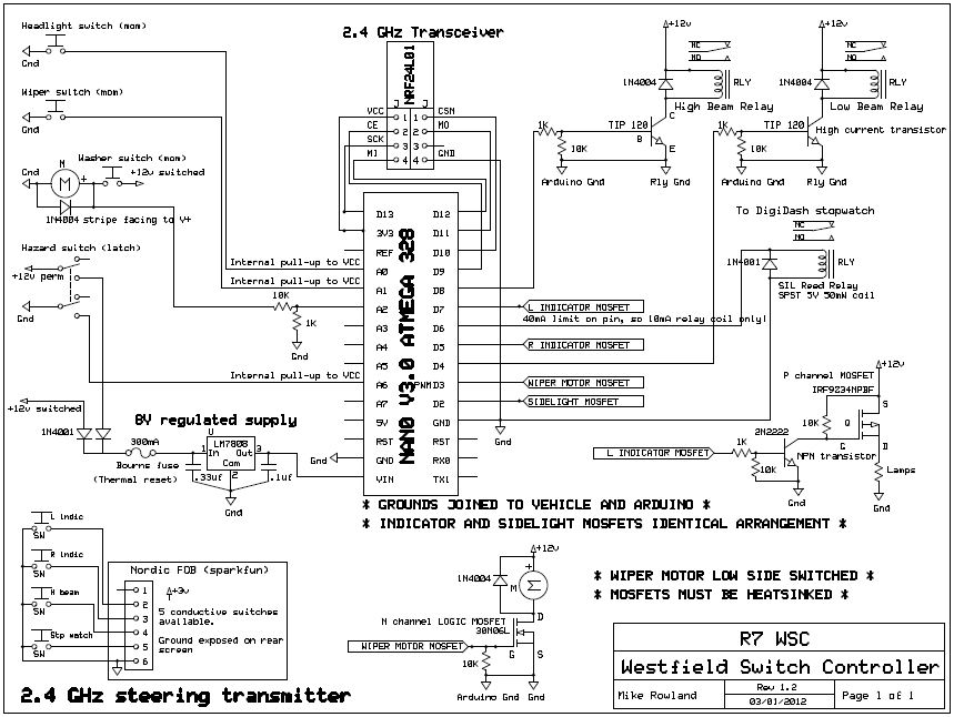
The core of the switch controller is an Arduino Nano microcontroller, which will serve as the interface between the dashboard switches, wireless steering wheel buttons, and the vehicle's lighting, indicators, windscreen wipers, and DigiDash2 GPS stopwatch. This setup facilitates...
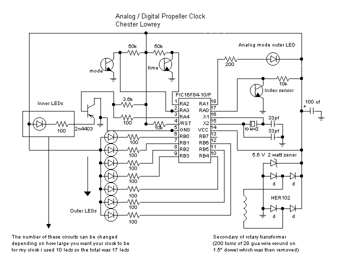
Propclocks are complex devices that utilize a PIC microcomputer operating at 10 MHz. The PIC serves as the core component, managing the timing of LED illumination to create the illusion of numbers and, in analog mode, hands suspended in...
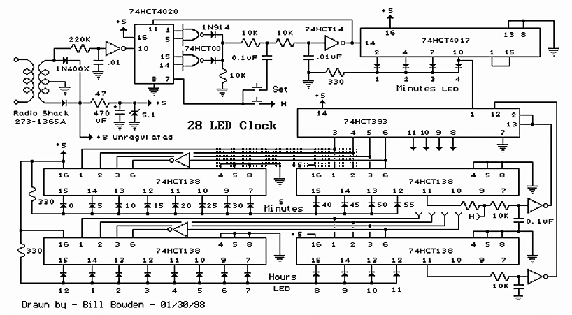
28 LED Clock Timer Circuit. This is a programmable clock timer circuit that uses individual LEDs to indicate hours and minutes. Twelve LEDs can be arranged in a circle to represent the 12 hours of a clock face, along with...

The circuit can be arranged in a circular format to represent the 12 hours of a clock face, with an additional 12 LEDs positioned in an outer circle to indicate 5-minute intervals within each hour. Four extra LEDs are...
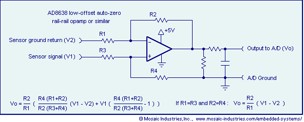
Ground loop offset errors and ground noise are eliminated by a differential amplifier or instrumentation amplifier before the analog-to-digital (A/D) conversion. The differential input amplifier addresses ground loop errors, allowing for precise measurement of non-isolated sensors. A simple operational...
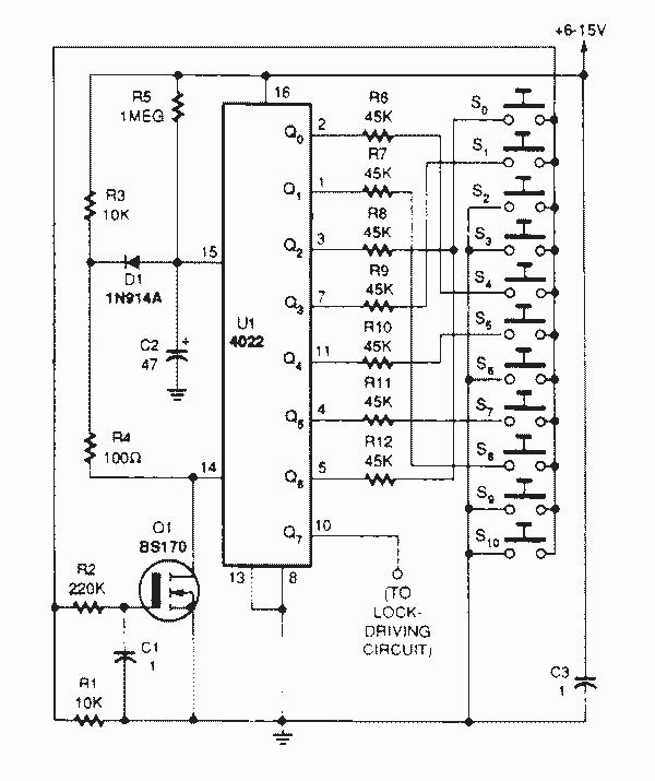
The heart of the lock is the 40022 octal counter. When first powered C2 is charged via R5 so the reset input of the counter is kept high. That causes output Q to go high while all the other...
Warning: include(partials/cookie-banner.php): Failed to open stream: Permission denied in /var/www/html/nextgr/view-circuit.php on line 713
Warning: include(): Failed opening 'partials/cookie-banner.php' for inclusion (include_path='.:/usr/share/php') in /var/www/html/nextgr/view-circuit.php on line 713