
6V to 220V Inverter Schematic

The inverter circuit converts a low voltage DC input, specifically 6 volts, into a high voltage AC output of 220 volts. This process typically involves several key components, including an oscillator, a transformer, and a rectifier.
The circuit begins with a DC voltage source of 6 volts, which can be supplied by batteries or a low-voltage power supply. The first stage of the inverter is the oscillator, which generates a square wave signal at a specific frequency, usually around 50 Hz or 60 Hz, depending on the application and regional power standards. This oscillator can be implemented using transistors or integrated circuits, which switch the DC input on and off rapidly to create the square wave.
The generated square wave is then fed into a transformer. The transformer plays a crucial role in stepping up the voltage. It consists of two coils of wire wound around a magnetic core. The primary coil receives the low voltage input, while the secondary coil outputs the higher voltage. The turns ratio between the primary and secondary coils determines the increase in voltage. For instance, a transformer with a turns ratio of 1:37 would convert 6 volts to approximately 220 volts.
After the AC voltage is produced, it may pass through a rectifier stage, especially if a pure sine wave output is desired. The rectifier converts the square wave AC into a smoother sine wave form, reducing distortion and making it suitable for powering sensitive electronic devices.
Additional components such as capacitors may be included to filter the output signal, ensuring a more stable and cleaner AC waveform. Protection elements like fuses or circuit breakers are also essential to safeguard the circuit against overloads and short circuits.
Overall, the 6V to 220V inverter circuit is a practical solution for applications requiring high voltage AC power from a low voltage DC source, commonly used in portable power supplies, renewable energy systems, and various electronic devices.6V to 220V Inverter Schematic. Starting from 6-Volt input on the DC current into 220-volt AC output.. 🔗 External reference
Related Circuits
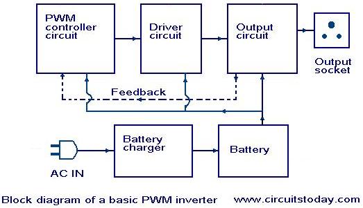
Nowadays, most inverters available in the market utilize Pulse Width Modulation (PWM) technology. Inverters based on PWM technology exhibit superior performance in several aspects compared to those designed using conventional methods. These PWM inverters typically employ MOSFETs in the...
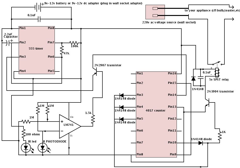
The schematic is provided below. It is recommended to construct it in three distinct sections, similar to the method demonstrated. The 555 timer circuit: connect pin 2 to pin... The schematic outlines a circuit design utilizing a 555 timer, a...
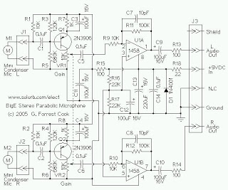
The mini condenser microphone converts sounds into an electrical signal. Resistor R1 provides bias for the condenser microphone's internal amplifier transistor. The 2N3906 PNP transistor acts as a low-noise microphone input amplifier. The 10K gain potentiometer is used for...
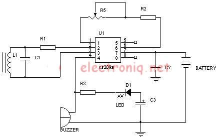
A simple metal detector electronic project circuit can be designed using the CS209A integrated circuit manufactured by Cherry Semiconductor. The CS209A integrated circuit is a bipolar monolithic integrated circuit intended for metal detection and proximity sensing applications. It incorporates...
This circuit diagram illustrates a resource replacement for 3V mercury cells or other small batteries. It has various applications, including powering a front panel multi-adapter with a digital thermometer in a computer. The circuit draws power from the PC,...
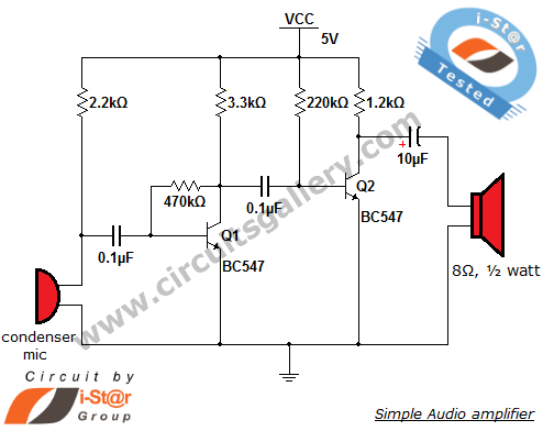
The output of the condenser microphone is coupled through a 0.1 µF coupling capacitor, which serves to eliminate DC components from the audio signal. Transistor Q1 is configured in a collector-to-base biasing mode, achieved with a 470kΩ resistor. This...