
Metal detector schematic circuit using CS209A

The circuit design for the metal detector using the CS209A integrated circuit involves several key components and configurations. The CS209A serves as the core of the metal detection system, leveraging its built-in features to facilitate the detection of metallic objects. The oscillator circuit, which is integral to the operation of this device, produces a frequency that is modified by the inductance of the coil. The 100 µH coil, essential for the detection mechanism, acts as the sensing element; its inductance varies when a metal object is nearby, resulting in a change in the oscillation frequency.
The external LC circuit, composed of the coil and a capacitor, establishes a resonant frequency that is sensitive to environmental changes. As metal objects come closer, the inductance increases or decreases, altering the resonant frequency and triggering the detection mechanism. The peak detection and demodulation circuitry processes the oscillation changes, allowing the comparator to determine when the frequency shifts beyond a preset threshold.
The output stages of the CS209A drive the LED and buzzer, providing immediate visual and auditory feedback when metal is detected. The adjustment of resistor R5 is crucial for calibrating the sensitivity of the detector. By setting the initial conditions with the LC circuit away from any metal sources, the system can be fine-tuned to ensure that it only activates in the presence of significant metallic interference.
In summary, the CS209A-based metal detector circuit is a compact and effective solution for metal detection applications, combining ease of setup with reliable performance. The design highlights the importance of the oscillator and LC circuit in achieving sensitivity to metal objects, making it suitable for various practical applications in fields such as security, archaeology, and hobbyist metal detecting.A very simple metal detector electronic project circuit can be designed using the CS209A integrated circuit manufactured by Cherry Semiconductor. The CS209A integrated circuit is a bipolar monolithic integrated circuit for use in metal detection proximity sensing applications.
The CS209A metal detector contains two on-chip current regulators, oscill ator and low-level feedback circuitry, peak detection/demodulation circuit, a comparator and two complementary output stages. The oscillator, along with an external LC network, provides controlled oscillations where amplitude is highly dependent on the Q of the LC tank.
The detector, is a single 100uH coil. The IC has an integral oscillator the choke forms part of an external LC circuit, it`s inductance being changed by the proximity of metal objects. It is the change in oscillation that is amplified and demodulated. Led 1 will light and the buzzer will sound when the inductance it`s changed. Set up is easy : R5 is adjusted with the LC away from any metal source so that the LED lights and buzzer sounds.
The control is backed off so that the LED goes out and buzzer stops. When the choke comes into contact with any metal object that alters its inductance, LED 1 and the buzzer will activate. 🔗 External reference
Related Circuits
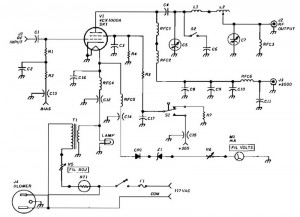
1500 Watt RF Amplifier circuit can be utilized to drive a transmitter antenna. It is also applicable for powering RF high power sources, microwave heating, and other uses. The 1500 Watt RF Amplifier circuit is designed to amplify radio frequency signals,...
Circuit diagram for a mini emergency lamp. This mini emergency lamp activates during power failures to provide cool white light in the room. It utilizes a 1-watt white LED to deliver adequate illumination. The circuit for the mini emergency lamp...

A diode is utilized in a temperature sensor application circuit. Silicon diodes VD1 and VD2 serve as the temperature sensors, exhibiting a temperature coefficient of silicon diodes. The circuit includes a constant current source, VT1, which provides a steady...
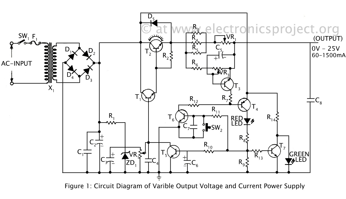
A ripple-free, short-circuit protected variable output voltage and current power supply is presented on this website as a verified project. The circuit diagram includes a description of various power supply circuits. This power supply circuit is designed to provide a...
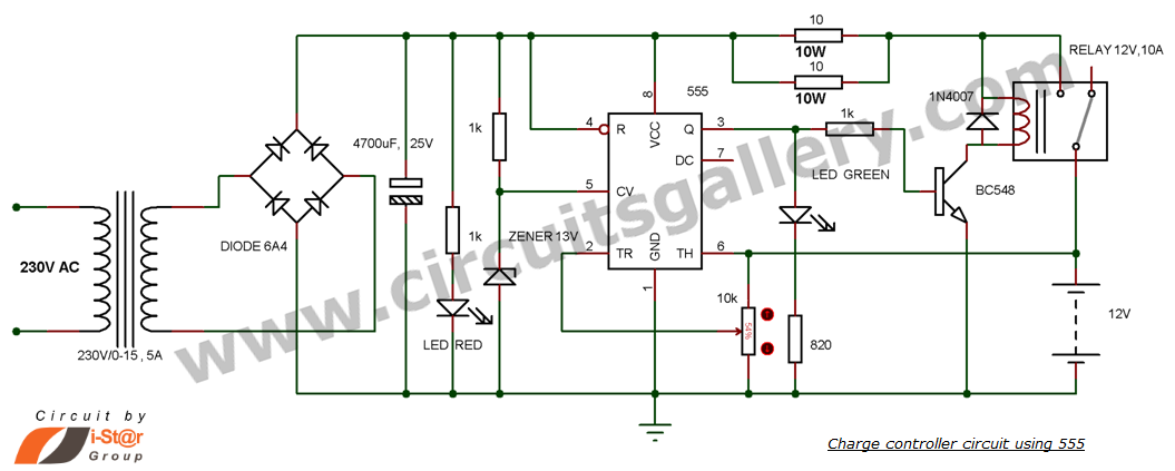
This is a simple DIY charge controller schematic created in response to a request from one of the readers on our Facebook page. The primary component of this automatic battery charger circuit is a 555 timer, which compares the...
This circuit consists of a light measurement circuit and a flash circuit, as illustrated in the accompanying figure. It is applicable in the POPTICS (a popular integrated camera), the Franka X-500, and the WIZEN-860S cameras. The light measurement circuit...