
7.2V Battery Replacement Power Supply For Camcorders
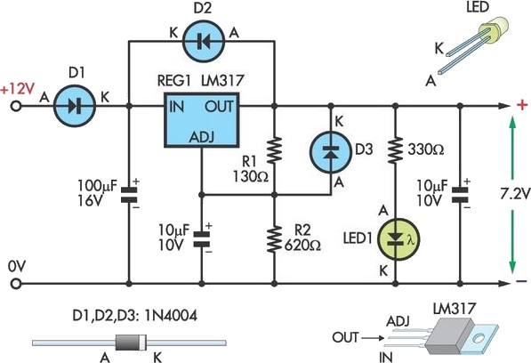
The circuit design centers around the LM317 voltage regulator, which is a versatile component capable of providing a stable output voltage. The LM317 requires a minimum input-to-output voltage differential, typically around 3V, to maintain regulation. Therefore, using a 12V SLA battery is suitable, as it exceeds the necessary input voltage for achieving a 7.2V output.
Resistors R1 and R2 are critical in setting the output voltage. The output voltage (Vout) can be calculated using the formula:
\[ V_{out} = V_{ref} \left( 1 + \frac{R2}{R1} \right) + I_{adj} \times R2 \]
Where \( V_{ref} \) is the reference voltage (approximately 1.25V), and \( I_{adj} \) is the adjustment pin current, which is typically negligible for most practical purposes. By selecting appropriate resistor values, the desired output voltage can be achieved.
For example, if R1 is set to 240 ohms and R2 is adjusted to 1.2k ohms, the output voltage would be approximately 7.2V. If the output voltage is lower than expected, reducing the resistance of R2 or increasing R1 can help achieve the correct voltage.
The LM317 should be mounted on a heatsink to dissipate heat generated during operation, especially under load conditions, to prevent thermal shutdown. The circuit design also includes an LED indicator that draws a small amount of current. This feature is useful for visual confirmation of circuit operation but should be considered when assessing the total quiescent current.
To ensure the longevity of the SLA battery, disconnecting the circuit when not in use is essential to avoid unnecessary drainage. This practice will help maintain the battery's charge and extend its lifespan, making it a reliable power source for the camcorder.
Overall, this circuit provides a practical solution for powering older camcorders with an easily sourced external battery, enhancing usability and functionality.This circuit lets an external 12V SLA battery power a camcorder which normally has an inbuilt 7. 2V battery. Such batteries can now be very difficult or expensive to obtain for earlier model camcorders. In essence, the circuit is a standard LM317 adjustable regulator with resistors R1 & R2 set to provide 7. 2V (depending on the accuracy of the 1. 25V internal reference). If the resulting output voltage is low, it can be increased by reducing the 130 resistor and vice versa. The circuit can be assembled on to the Eliminator PC board or the simple DC power supply PC board. The regulator should be fitted with a flag heatsink. Note that the circuit should be disconnected from the battery when not in use, otherwise its quiescent current (from the LED and regulator) will flatten the SLA battery.
🔗 External reference
Related Circuits
The primary issue with the design of a stereo amplifier that includes a total bass driver is that the signals from the left and right channels eventually become combined. This summation process minimizes the separation between channels, compromising the...
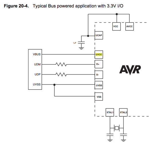
Since the microcontroller unit (MCU) is powered through USB, the common zero voltage should align with the supply voltage and thus be connected to the 0V (UVSS) line. In electronic circuit design, it is essential to ensure that the ground...
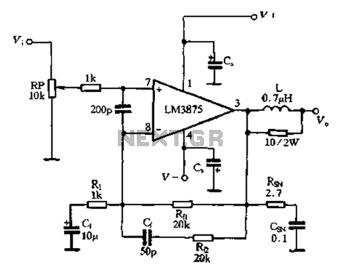
The 875T and LM3876T are high-performance 40W power amplifier integrated circuits (ICs). They operate within a frequency range of 20Hz to 20kHz with a continuous average power output under an 8-ohm load and exhibit a distortion level of only...
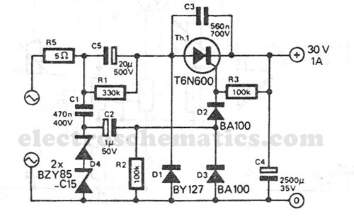
This transformerless power supply circuit is designed for medium current applications. During the negative half period, the capacitor C5 is charged to the peak voltage of the network. The positive half wave will trigger the thyristor, allowing the electric...
One of the major problems that must be addressed in electronic circuit design is the generation of low voltage DC power supply from mains power to energize the circuit. In electronic circuit design, the conversion of mains AC voltage to...
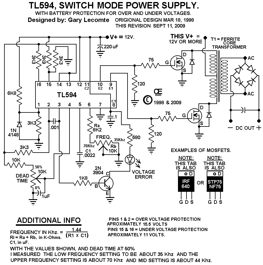
This circuit is designed for individuals needing to boost or drop a voltage. The output operates at high frequency but can be rectified and filtered to provide a DC output. When rectifying high frequencies, it is essential to utilize...
Warning: include(partials/cookie-banner.php): Failed to open stream: Permission denied in /var/www/html/nextgr/view-circuit.php on line 713
Warning: include(): Failed opening 'partials/cookie-banner.php' for inclusion (include_path='.:/usr/share/php') in /var/www/html/nextgr/view-circuit.php on line 713