
Capacitor Power Supply Circuit

In electronic circuit design, the conversion of mains AC voltage to a low voltage DC power supply is a critical process. This typically involves several stages, including voltage transformation, rectification, filtering, and regulation.
1. **Voltage Transformation**: The first step is to step down the mains voltage (usually 120V or 240V AC) to a lower AC voltage using a transformer. The transformer is selected based on the required output voltage and current specifications. It is essential to ensure that the transformer is rated for the appropriate power level to handle the load without overheating.
2. **Rectification**: After the AC voltage is stepped down, the next step is rectification, which converts the AC voltage to pulsating DC. This is commonly achieved using a diode bridge rectifier, which consists of four diodes arranged in a bridge configuration. The rectifier allows current to flow in one direction, effectively converting both halves of the AC waveform into a unidirectional flow.
3. **Filtering**: The output from the rectifier is a pulsating DC voltage that contains ripples. To smooth out these ripples and produce a more stable DC output, a filtering capacitor is used. The capacitor charges during the peaks of the pulsating DC and discharges during the troughs, thereby reducing the voltage fluctuations. The value of the capacitor is chosen based on the load current and the acceptable ripple voltage.
4. **Regulation**: Finally, to ensure a constant output voltage regardless of variations in input voltage or load conditions, a voltage regulator is implemented. This can be a linear regulator, such as the 7805 for 5V output, or a switching regulator, which is more efficient for higher power applications. The regulator maintains the output voltage within specified limits, providing stability for sensitive electronic components.
The design of a low voltage DC power supply from mains involves careful consideration of component ratings, safety standards, and efficiency. Proper isolation and protection mechanisms must also be integrated to safeguard against electrical hazards and ensure reliable operation.One of the major problems that is to be solved in an electronic circuit design is the production of low voltage DC power supply from Mains to power the cir.. 🔗 External reference
Related Circuits
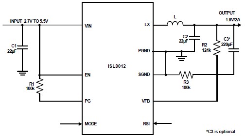
The ISL8012 is a high-efficiency, monolithic, synchronous step-down DC-DC converter that can be designed into a simple electronic project. It supports a maximum continuous output current of up to 2A from an input supply range of 2.7V to 5.5V....
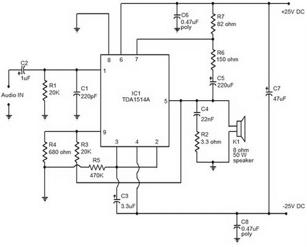
This document provides a circuit diagram of a car stereo. It includes a circuit diagram of a Class B 15 Watts audio amplifier designed using a dual op-amp and a transistor. The 15 W Class B audio amplifier circuit...
The 0 to 130-volt voltmeter and neon "AC PWR" lamp provide an average indication of AC power. The fuse and metal oxide varistor (MOV) protect the monitor against overvoltage spikes. Four 1N4004 diodes rectify the AC voltage, generating negative-going...
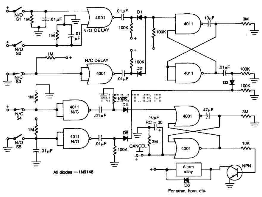
This circuit features open and closed loop contacts (switches 1, 2, 3) that activate the alarm, which remains on for a duration of 5 to 10 minutes. The triggering delay for entrance and exit is set to 27 seconds....
Detects the amount of salt contained in liquid foods, featuring a three-level LED indicator. This circuit is designed to detect the approximate percentage of salt concentration. The salt detection circuit operates by utilizing a conductivity sensor that measures the ionic...
This is a simple NiCd battery charger powered by solar cells. A solar cell panel or an array of solar cells can charge a battery at more than 80% efficiency. The described circuit functions as a basic NiCd battery charger...