
7 band audio graphic equalizer circuit

The audio equalizer circuit is designed to manipulate audio signals by adjusting the amplitude of specific frequency bands, thereby allowing for a customized listening experience. The circuit typically uses multiple bands, each tuned to a specific frequency range, and operates by employing a gyrator circuit, which simulates an inductor using active components. In this configuration, the gyrator provides a variable inductance that can be finely adjusted through the potentiometer, allowing for precise control over the frequency response.
The three formulas integral to the operation of the circuit serve distinct purposes. The first formula calculates the center frequency (f) of each band, determining where the maximum gain occurs. The second formula establishes the relationship between the quality factor (Q) and the capacitor ratio, which affects the bandwidth of the frequency response. A higher Q indicates a narrower bandwidth, resulting in a sharper peak at the center frequency. Conversely, a lower Q yields a broader response, which can be beneficial for more general adjustments.
The impedance formula is crucial for understanding how the circuit interacts with the audio source and load. The resistive component represents the inherent resistance of the circuit elements, while the capacitive and inductive contributions modify the overall impedance at different frequencies. This interaction plays a significant role in the circuit's ability to filter and amplify specific audio signals effectively.
Operational amplifiers are central to the audio equalizer's functionality, as they provide the necessary gain and buffering for the audio signals. The op-amp configuration can be set up in various ways, such as inverting or non-inverting modes, to achieve the desired signal processing characteristics. The tuning of the gyrator circuit, in conjunction with the op-amp, allows for a versatile and responsive equalization process, making this audio equalizer suitable for a wide range of applications, from home audio systems to live sound reinforcement.This is circuit for audio equalizer that is very common as commercial products (for Hi-fi, car audio and stage use) but circuits for them are very rarely published. This circuit is like as equalizer bands. Here`s the circuit diagram of the audio equalizer project. The circuit includes three formula: one which gives f, the centre frequency of the b and. The second shows how the Q is related to the capacitor ratio. The third shows the impedance presented by the circuit. Note that this includes 3 terms, the first purely resistive, the second is the capacitive contribution from C1 and the third is an inductive term from the gyrator. The rest of the circuit is simply an op-amp. If you consider a `tuned circuit` (the gyrator) hanging from the pot slider, it is being connected either to the positive input or the negative to a variable extent.
One will increase the response at the turned frequency and the other will decrease it. 🔗 External reference
Related Circuits
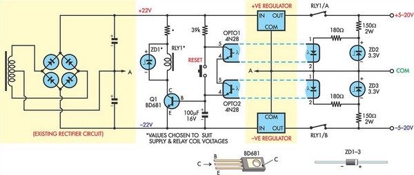
This circuit was designed to protect a dual rail power supply from shorts across the two rails. It uses an optocoupler to monitor each supply rail, with the internal LEDs powered from ZD2 and ZD3 and the associated resistors....
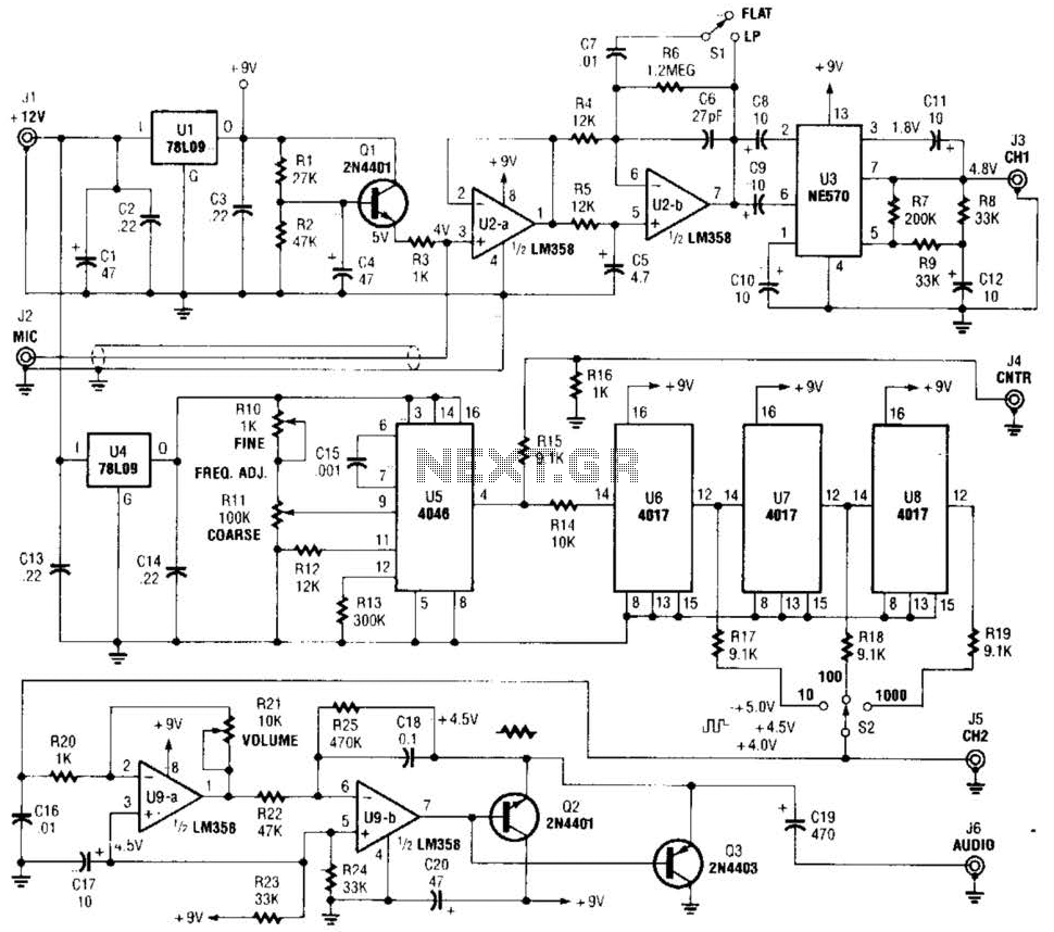
The precision audio frequency generator consists of several sub-circuits: an audio amplifier/filter circuit, an automatic level control, a variable voltage-controlled oscillator, a frequency divider circuit, an integrator, and an audio output amplifier. An electret microphone element is utilized to...
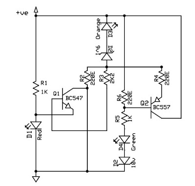
This circuit is a 12V battery checker that utilizes three LEDs to indicate different voltage levels. The red LED illuminates when the battery voltage is between 8V and 10V, the orange LED activates at voltages ranging from 10.5V to...

This is a simple design schematic for a phase control circuit that regulates the power delivered to an AC load. The phase control circuit modifies the AC waveform, allowing for variations such as full cycle, half cycle, zero cycle,...
When the unit is positioned near a live conductor, whether insulated or buried in plaster, capacitive coupling occurs between the live conductor and the probe. This interaction activates the counter, resulting in the LED flashing five times per second,...
The K-type thermocouple is a commonly used temperature sensor in industrial production and scientific experiments. It can measure temperatures ranging from 0 to 1300 degrees Celsius in various applications, including direct measurements of gas, liquid, and solid surfaces. Its...