
short circuit protection for balanced

The circuit design incorporates a dual rail power supply protection mechanism utilizing optocouplers for voltage monitoring. The optocouplers are configured such that their internal light-emitting diodes (LEDs) are powered by Zener diodes ZD2 and ZD3, which stabilize the voltage across the LEDs and ensure consistent operation. The associated resistors are selected to limit the current through the LEDs to safe levels, thus preventing damage to the components.
In normal operation, when the supply rails are functioning correctly, the LEDs in the optocouplers illuminate, activating the internal phototransistors. This activation allows current to flow through transistor Q1, which in turn energizes relay RLY1. The energized relay maintains the connection between the power supply rails, allowing the system to operate normally.
In the event of a short circuit across either rail, the corresponding optocoupler's LED will turn off, resulting in the deactivation of its internal phototransistor. This deactivation removes the base current from transistor Q1, causing it to turn off. Consequently, relay RLY1 is de-energized, breaking the connection between the supply rails and protecting the circuit from potential damage due to overcurrent conditions.
To restore operation after a fault condition, a reset button is incorporated into the design. Pressing this button re-enables the circuit, allowing the optocouplers to function normally again, provided that the short circuit has been cleared.
The selection of ZD1 and its associated resistor is critical, as these components must be appropriately rated to handle the supply voltage and the relay coil voltage. This ensures that the circuit operates effectively under different load conditions while providing reliable protection to the power supply system.This circuit was designed to protect a dual rail power supply from shorts across the two rails. It uses an optocoupler to monitor each supply rail, with the internal LEDs powered from ZD2 and ZD3 and the associated resistors. While the LEDs are on, the optocouplers internal transistors are both turned on which ensures that transistor Q1 is on and
relay RLY1 is energised. If either rail is short-circuited, the associated optocoupler is turned off, robbing Q1 of base current and the relay then drops out to disconnect the supply rails. Operation is restored by pressing the reset button. The value of ZD1 and the associated resistor should be chosen to suit the supply and relay coil voltages.
🔗 External reference
Related Circuits
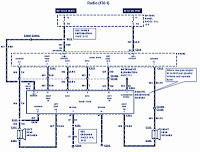
The section of the 1996 Ford Windstar wiring diagram includes details on power distribution, common connections, rear circuits, ignition systems, the fuse panel, battery connections, instrument illumination, radio wiring, left rear speaker connections, remote headphone module, solid-state components, and...

The following circuit illustrates a Bedside Lamp Timer Circuit Diagram. This circuit is based on the CD4060 integrated circuit. Features: An LED illuminates for approximately 25 seconds. The Bedside Lamp Timer Circuit utilizes the CD4060 IC, which is a versatile...
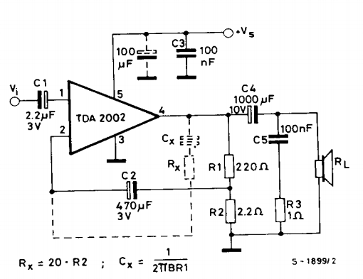
This is a power amplifier circuit built using the TDA2002 power amplifier IC module. It serves as a replacement for the original LM383, which is no longer available. The circuit is easy to assemble and requires a minimal number...
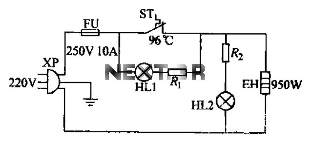
The 220V electric vibrator features a clip for insertion, with FU representing the fuse. ST indicates an inverter-like device, while HL1 and HL2 serve as indicators for insulation and heating. The EH component functions as the heater. When the...
This 300W RF power amplifier for an FM transmitter utilizes 2 x TP9383 transistors. It operates within the 88 - 108 MHz frequency band. The 300W RF power amplifier is designed specifically for FM transmission applications, providing high power output...

A decrease in the resistance of the CDS cell when light strikes it activates latch A and B, enabling tone oscillator C and D, which produces an output of about 1000 Hz. RA sets the trip level. SI resets...