
A 4-Digit Keypad Controlled Switch circuit

The universal four-digit alarm control keypad circuit is designed to provide a versatile and user-friendly interface for various electronic applications. The core functionality of this circuit revolves around a microcontroller that interprets the input from the keypad, allowing users to enter a four-digit code to control the relay contacts.
The keypad typically consists of a matrix arrangement of buttons, each corresponding to a digit from 0 to 9, as well as additional keys for functions such as enter or reset. The microcontroller reads the state of the buttons and processes the input. Upon successful entry of the correct code, the microcontroller activates the relay.
The relay, which can be a SPCO or SPDT type, serves as the output device in this circuit. When the relay is energized by the microcontroller, it can control a variety of loads, functioning as a general-purpose switch. This flexibility allows the circuit to be integrated into different systems, such as security alarms, home automation systems, or any application requiring a controlled switch mechanism.
In terms of power supply, the circuit may require a regulated voltage source compatible with the microcontroller and relay specifications. Proper decoupling capacitors should be included to ensure stable operation. Additionally, it is advisable to incorporate protection diodes across the relay coil to prevent back EMF from damaging the microcontroller.
For enhanced functionality, the circuit can be designed to include features such as LED indicators for status feedback, sound alarms for incorrect code entries, and additional inputs for sensor integration. With these enhancements, the universal four-digit alarm control keypad circuit can be tailored to meet specific user requirements while maintaining reliability and ease of use.This is a Universal version of the Four-Digit Alarm Control Keypad. I have modified the design to free up the relay contacts. This allows the circuit to operate as a general-purpose switch. I`ve used a SPCO/SPDT relay - but you can use a multi-pole relay if you wish.. 🔗 External reference
Related Circuits

This is an automatic light dimmer circuit that eliminates the need for manual adjustment of light levels. It utilizes a Light Dependent Resistor (LDR) to detect ambient light conditions, which in turn controls a Triac to adjust the brightness...
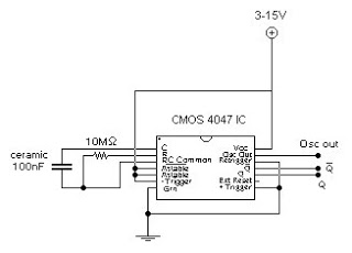
This circuit generates a digital square wave that can be displayed directly or utilized to drive additional circuits. It employs the CMOS 4047 Low-Power Monostable/Astable Multivibrator, as referenced in Tom Duncan's "Adventures with Digital Electronics" book, to control a...
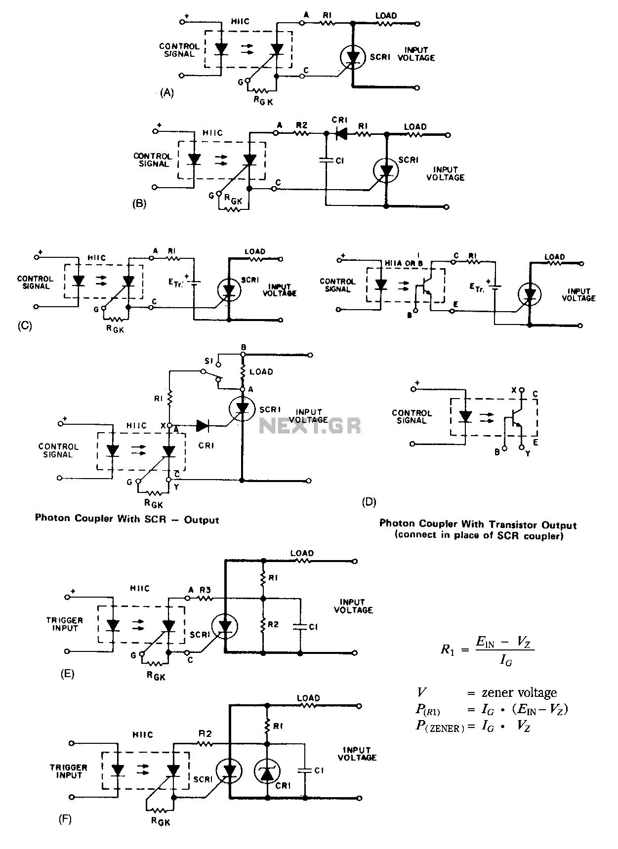
A basic circuit to trigger a silicon-controlled rectifier (SCR) is illustrated in Figure 67-1A. This circuit has the limitation that the blocking voltage of the photonic coupler output device dictates the circuit's blocking voltage, despite the SCR's higher voltage...
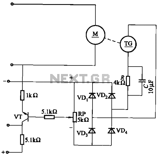
The capacitor C is part of the speed differential negative feedback system. The adjustment potentiometer RP allows for changing the amount of negative feedback. Both components can be utilized simultaneously within the circuit. The voltage (or speed) will only...
The i-TRIXX circuit is designed to prevent issues for individuals traveling in a caravan. It provides an early warning system through an illuminated LED, alerting users when the battery charge is low, thereby preventing the inconvenience of being unable...
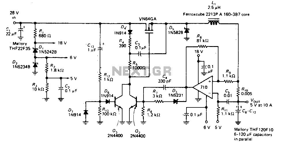
This circuit provides a regulated DC output with less than 100 mV of ripple for microprocessor applications. The required operating voltages are derived from a bleeder resistor network connected across the unregulated 28 V supply. The output of the...