
7 Segment Digital Clock Circuit Using IC 5314 PCB

The digital clock circuit primarily features the MM5314 integrated circuit, which is specifically designed for timekeeping applications. This IC is capable of generating accurate time signals and driving the common anode seven-segment displays directly. The circuit is configured to operate at standard power line frequencies of either 50 Hz or 60 Hz, ensuring compatibility with various electrical systems worldwide.
The common anode seven-segment displays used in this circuit consist of seven individual segments for each digit, allowing for the representation of numerals from 0 to 9. Each display is connected to the MM5314, which controls the illumination of the segments based on the current time values. The configuration allows for a clear and easy-to-read time display, suitable for various environments.
The clock can be set to display time in either a 12-hour or 24-hour format, which can be selected based on user preference. This feature adds flexibility and convenience for users accustomed to different timekeeping styles. The MM5314 IC manages the timekeeping logic, including the counting of seconds, minutes, and hours, while also providing reset functionality for setting the time.
This digital clock circuit is an excellent choice for educational purposes, particularly for college students engaging in electronics projects. Its simplicity, combined with the absence of complex components such as microcontrollers, makes it an ideal project for learning about digital electronics and timekeeping mechanisms. The design emphasizes fundamental concepts such as frequency division, binary counting, and display driving techniques, all of which are crucial in the field of electronics.This circuit diagram of digital clock uses six common anode seven segment displays to show the time. It needs neither micro controllers or PIC for it`s operation. It`s a MM5314 IC driven digital clock operating at 50 Hz or 60 Hz, and 12 or 24 hour display format. It`s very suitable for college mini projects. 🔗 External reference
Related Circuits
The project described in this article is a constant Q, fully expandable graphic equaliser. Where most "conventional" graphic EQ circuits have a Q that is dependent on the setting of the pot, this one maintains the same Q at...
The circuit operates based on a desired temperature setting. It can be utilized for various applications, such as turning on a fan at a specified temperature or activating an emergency temperature alarm. The power supply for the circuit can...
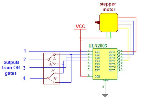
Wireless stepper motor speed control project using a laser and IC555. This project provides insights into the fundamentals and circuit construction for controlling the speed of a wireless stepper motor utilizing a laser and the IC 555 timer. The project...
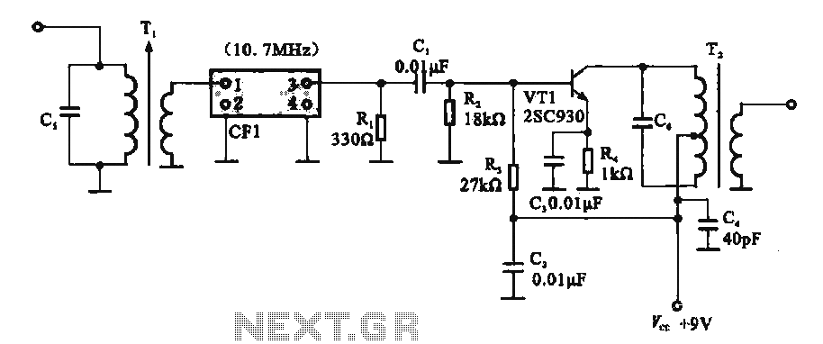
This circuit features a ceramic filter integrated with an FM intermediate frequency (IF) amplifier. The FM IF amplifier circuit primarily consists of an input variable voltage regulator (T), ceramic filters (CF1), and additional components such as the IF amplifier...
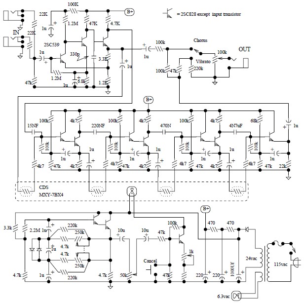
The Univibe is a footpedal-operated phaser or phase shifter designed to generate chorus and vibrato simulations for electric organs or guitars. It was introduced in the 1960s by Shin-ei, with the intention of emulating the "Doppler sound" characteristic of...
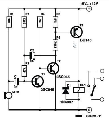
This circuit features a simple, highly sensitive capacitive ON/OFF switch pad that changes the state of a latch and activates an LED without requiring physical contact. The pad can be insulated, and a range of 12mm is easily achievable...