
70 Interesting Circuits
In addition, the circuit includes an emergency light feature. As long as the power supply is operational, transistor Q1 remains in a conductive state. Since the base of transistor Q2 is linked to the collector of Q1, both Q2 and Q3 remain non-conductive, keeping the lamp off. An LED remains illuminated as long as the power supply is active. When the power supply fails, the base drive to Q1 is lost, causing Q1 to stop conducting. Consequently, its collector voltage rises to the battery voltage, activating the lamp immediately. The load current is then sourced from the battery. Upon restoration of the power supply, Q1 resumes conduction, turning off Q2 and Q3, which subsequently switches off the lamp. This design effectively ensures the lamp is only activated in the event of a power failure, providing a reliable emergency lighting solution.This circuit will detect AC line currents of about 250mA or more without making any electrical connections to the line. Current is detected by passing on of the AC lines through an inductive pickup (L1) made with a 1 inch diameter U-bolt wound with 800 turns of #35 magnet wire.
The pickup can be made from other iron type rings or transformer cores that allows enough space to pass one of the AC lines through the center. Only one of the current carrying lines, either the line or the neutral should be put through the center of the pickup to avoid the fields cancelling. If you make a 3-turn loop with say the active line, and pass a straight rod such as a metal bolt, containing 400 or more turns through the centre of the 3-turns, you will produce a very sensitive pick-up.
The magnetic pickup produces about 4 millivolts for AC line current of 250mA, or AC load of around 30 watts. The signal from the pickup is increased about 200 times at the output of the op-amp pin 7 which is then peak detected by the capacitor and diode connected to pin 7.
The second op-amp is used as a comparator which detects a voltage rise greater than the diode drop. The minimum signal needed to cause the comparator stage output to switch positive is around 800mV which corresponds to about a 30 watt load on the AC line. The output of the 1458 op-amp will only swing within a couple volts of ground so a voltage divider (1k/470) is used to reduce the no signal voltage to about 0.
7 volts. An additional diode is added in series with the transistor base to ensure it turns off when the op-amp voltage is 2 volts. You may get a little bit of relay chatter if the AC load is close to the switching point so a larger load of 50 watts or more is recommended.
The sensitivity can be increased by adding more turns to the pickup. A 12v relay is connected across the 12v supply. When the output is shorted, the 12v falls to 0v and the relay drops-out. The contacts open the 12v is reapplied to the relay and it will "chatter" if the short is not removed. Three reed switches are at the heart of the circuit, one fitted to each door. They close when a door is opened. An associated LED lights when a door is opened. The remainder of the circuit is powered by either D1, D2 or D3. However the 555 is not enabled until pin 4 goes high and this requires the output of either IC1a or IC1b to go high.
In turn, this requires either pin 1, 2 or 4 go high and this happens when a door opens. Because the high on each pin is only momentary (i. e. about 1/3 second, while C1, C2 or C3 is charging) there is only a short burst of buzzer activity (two brief beeps) at each door opening, after which it goes mute again. So the beep calls attention to the fact that a door has opened and the LED indicates which door, staying lit until [i door is closed.
If another door opens before the first door is closed, there is another beep and another LED lights. The circuit above is too complex. It is very poorly designed. The 3 signals diodes are doing NOTHING. The are simply across each other! One diode could be placed in the supply line to the 555 if it is needed for the reset line to work correctly. R7 is not needed as the output is taken to the pins 2&6 and the 74LS32 chip can be replaced by 3 x 470u electrolytics.
Here is a circuit of an emergency light. As long as the power supply is present, transistor Q1 conducts. Since the base of the transistor Q2 is connected to the collector of Q1, transistor Q2 and Q3 do not conduct and hence the lamp remains off. LED glows as long as the supply is present. When the power supply fails, the base drive to Q1 disappears. Thus Q1 stops conducting and its collector voltage jumps to battery voltage and starts conducting, switching on the lamp instantly.
The load current is supplied by the battery. Whenever the power supply is restored, Q1 starts conducting turning Q2 & Q3 off and the lamp is switched off. Transistor 🔗 External reference
Related Circuits
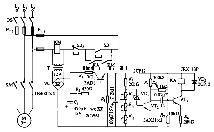
A P-type transistor (VT2, VT3) and other components form a common emitter-coupled trigger, functioning as a Schmitt trigger device. This setup serves as a switching circuit to detect changes in the resistance of a PTC thermistor, thereby controlling the...
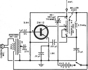
It had been a little over a decade since the invention of the transistor when this article appeared in the August 1959 edition of Popular Electronics. Transistors were still a mystery to many, including engineers, technicians, and hobbyists. Author...
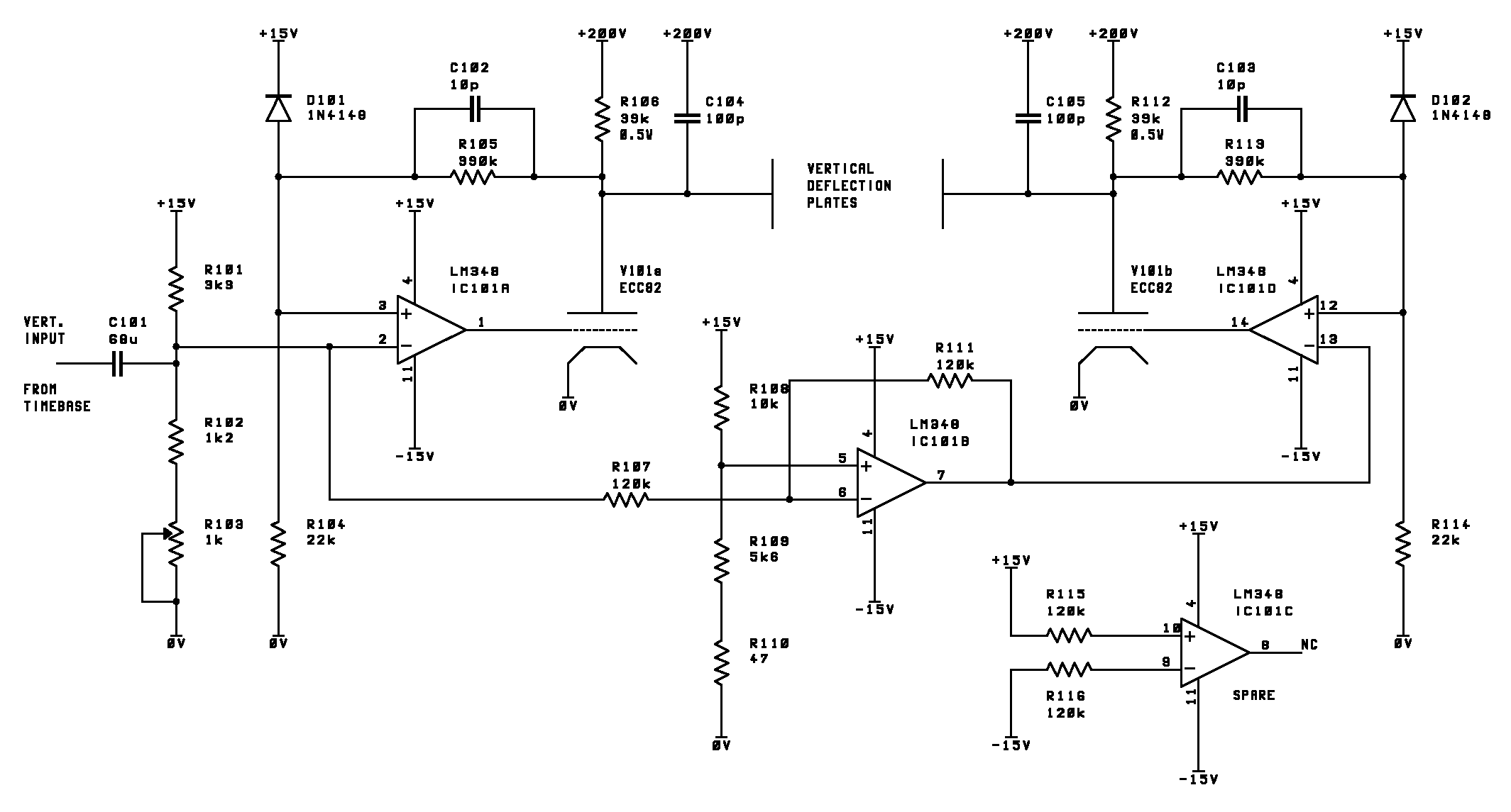
This page outlines the development of electronics for displaying a monochrome video image on an electrostatic oscilloscope tube. This work complements the Electron Optics section in the Experiments category. The primary objective is to showcase a moving video image...
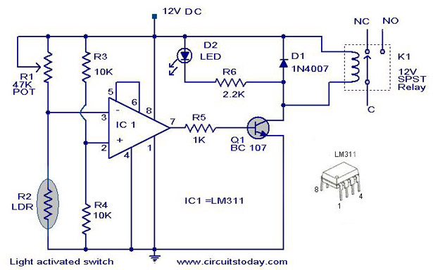
A simple light-activated switch circuit diagram utilizes the National Semiconductor comparator IC LM311 and a light-dependent resistor (LDR). The circuit functions as a voltage comparator, with the non-inverting input of IC1 receiving a reference voltage of 6V through resistors...
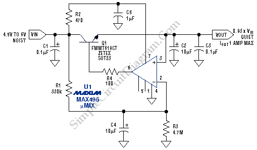
This low noise audio power supply circuit can reduce noise and ripple voltage by 40 dB over the 100 Hz to 20 kHz audio range. In portable applications such as... This low noise audio power supply circuit is designed to...

To prevent deep discharge that can damage or shorten the life of a rechargeable battery, it is essential to disconnect its load before the battery is completely discharged. The circuit protects against AC line disturbances by switching off the...
Warning: include(partials/cookie-banner.php): Failed to open stream: Permission denied in /var/www/html/nextgr/view-circuit.php on line 713
Warning: include(): Failed opening 'partials/cookie-banner.php' for inclusion (include_path='.:/usr/share/php') in /var/www/html/nextgr/view-circuit.php on line 713