
Low Noise Power Supply for Audio Circuits

This low noise audio power supply circuit is designed to significantly minimize electrical noise and ripple voltage, achieving a reduction of 40 dB in the frequency range of 100 Hz to 20 kHz. This performance is critical for audio applications where clarity and fidelity are paramount, particularly in portable devices that may be susceptible to interference from various sources.
The circuit typically employs a combination of linear voltage regulation and filtering techniques to achieve its low noise specifications. A well-designed low-dropout (LDO) regulator can be used to maintain a stable output voltage while rejecting high-frequency noise. To further enhance performance, capacitors with low equivalent series resistance (ESR) are recommended for decoupling and smoothing the output. These capacitors should be placed as close as possible to the load to minimize inductive effects and provide optimal transient response.
Additionally, the incorporation of ferrite beads or inductors in series with the power supply lines can help suppress high-frequency noise generated by digital circuits or RF interference. The layout of the circuit board is also crucial; a star ground configuration is advisable to prevent ground loops and ensure that the sensitive audio signals are not compromised.
For portable applications, considerations such as power efficiency and thermal management are essential. The use of switching regulators, when designed properly, can offer a good balance between efficiency and noise performance, although they require careful filtering to mitigate switching noise.
Overall, this low noise audio power supply circuit is an essential component for high-fidelity audio systems, ensuring that audio signals remain clean and free from unwanted interference, thereby enhancing the overall listening experience.This low noise audio power supply circuit can reduces noise and ripple voltage by 40dB over the 100Hz to 20kHz audio range. In portable application such as.. 🔗 External reference
Related Circuits
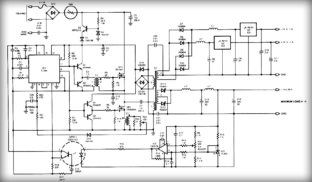
This power supply employs two VN400A 400-Volt MOSFETs arranged in a half-bridge configuration. The outputs provide +5V at 20A and +15V at 1A. Low-current outputs utilize three-terminal regulators, allowing for either 12 Volts or 15 Volts to be achieved...
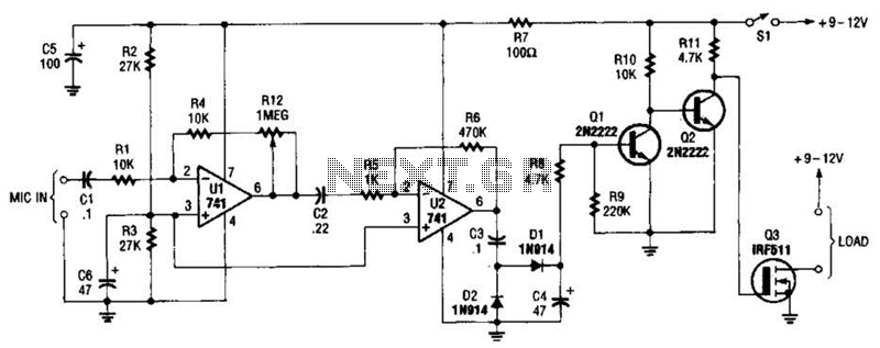
The audio-controlled switch utilizes a pair of 741 operational amplifiers, two 2N2222 general-purpose transistors, a hexFET, and several supporting components to create a circuit capable of activating devices such as a tape recorder, a transmitter, or virtually any other...
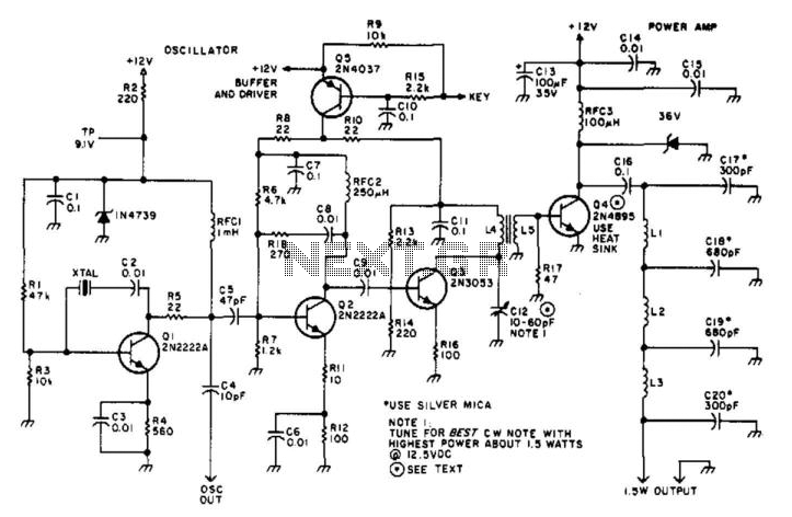
Suitable for amateur use, this 1.5-W transmitter operates on a 12-V supply. Q1 functions as an oscillator utilizing a surplus FT243 crystal. Q2 serves as a buffer driver and is activated through the keying transistor Q5. Q3 acts as...
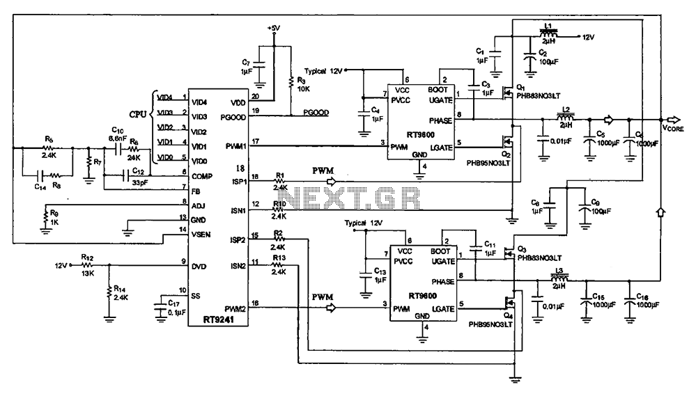
A typical computer motherboard CPU power supply circuit is primarily composed of the main power supply management chip RT9241 and additional components from the power management chip RT9600. The voltage command signal from the CPU is input into the...
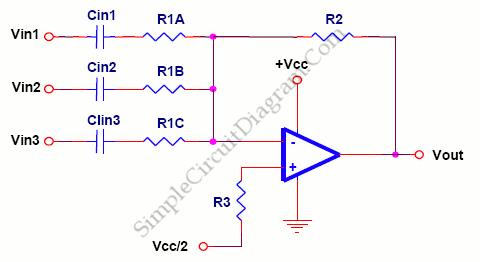
The foundation of an audio mixer is an inverting summing circuit. In practical audio mixers, a single-supply voltage is rarely utilized. To enhance dynamic range, ... The inverting summing circuit serves as a fundamental building block in audio mixing applications,...
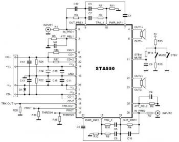
This is a stereo amplifier circuit diagram. The amplifier will produce stereo output channels with a power audio output that can reach up to 70W for each channel. The amplifier is built using the STA550 chip from STMicroelectronics. It...