
72 LED Clock

The clock circuit utilizes a total of 72 LEDs, with 60 dedicated to minute indication and 12 for hour representation. The 74HCT164 is an 8-bit serial-in, parallel-out shift register, which is essential for managing the LED outputs. In this design, eight of these shift registers are connected in a cascade configuration, enabling a single bit to circulate through all 60 LEDs. This configuration allows for the representation of each minute in a standard hour.
The power supply circuitry is designed to provide a stable voltage suitable for the operation of the LEDs and the shift registers. Typically, a regulated DC voltage source, such as +5V, is utilized to ensure consistent performance. The time base circuitry, likely based on a crystal oscillator or a timer IC, generates the necessary clock pulses to drive the shift registers. This clock signal is crucial for shifting the bits through the registers at the correct intervals, thus illuminating the appropriate LED for the current minute.
In terms of LED operation, each minute corresponds to a unique LED being lit, while the hour indication is handled separately with 12 LEDs, which may be controlled by another set of shift registers or a different logic mechanism. The cascading of the shift registers allows for seamless transition from one minute to the next, with the LEDs illuminating in a sequential manner, providing a clear visual representation of the time.
Overall, this clock design effectively combines digital logic with visual output, utilizing standard components to achieve a functional and visually appealing timekeeping device.In the circuit, 60 individual LEDs are used to indicate the minutes of a clock and 12 LEDs indicate hours. The power supply and time base circuitry is the same as described in the 28 LED clock circuit above. The minutes section of the clock is comprised of eight 74HCT164 shift registers cascaded so that a single bit can be recirculated through the 60 stages indicating the appropriate minute of the hour
🔗 External reference
Related Circuits
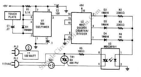
This is a three-mode lamp dimmer circuit with touch control. This circuit can be used to control a lamp in three operation modes: dim, off, and bright. It utilizes a NE555 timer. The three-mode lamp dimmer circuit designed with touch...
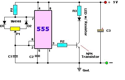
A user is new to the forum and has limited experience in DIY electronics. The current project involves creating a battery-powered LED dimmer circuit. The objective of the project is to design a battery-operated LED dimmer circuit that allows for...
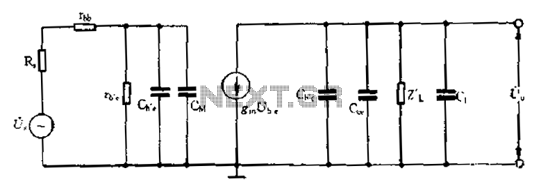
Common emitter amplifier circuit with resistance and capacitance coupling. The common emitter amplifier circuit is a fundamental configuration in analog electronics, widely utilized for its ability to amplify voltage signals. This circuit employs a bipolar junction transistor (BJT) as the...

This transistor has only one IC tester and can test all types of transistors. With two LEDs indicating the type of the transistor is NPN or PNP. The circuit uses a CMOS 4049 IC. The test transistor to terminals...

This chip from Texas Instruments is easy to integrate into designs and is suitable for the assembly of lighting devices. A consistent quality and expected performance can be easily achieved. The complete circuit consists of a control integrated circuit...
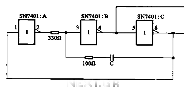
The clock signal generating circuit utilizes an RC configuration, commonly applicable in most TTL systems. This circuit requires a set of six inverters, specifically three inverters from the SN7401 series. The clock frequency is determined by the values of...