
Transistor Tester with LEDs

The circuit described functions as a universal transistor tester, capable of testing both NPN and PNP transistors. The core component of the circuit is the CMOS 4049 integrated circuit, which is configured to provide the necessary logic for determining the operational state of the transistor under test.
When a transistor is connected to the designated terminals labeled "B" (base), "C" (collector), and "E" (emitter), the circuit is powered on. The testing process begins, and if the transistor is functioning correctly, one of the two LEDs will illuminate. Specifically, if the transistor is a PNP type, LED D1 will light up, while for an NPN transistor, LED D2 will activate. If neither LED lights up, it indicates that the transistor is faulty.
The circuit includes several passive components that play a crucial role in its operation. Resistor R1, valued at 680 kOhms, is likely used to limit the current flowing through the LEDs, ensuring they operate within safe limits. Resistor R2, with a value of 470 ohms, serves a similar purpose, providing current limiting for the base of the transistor under test.
Resistors R3 and R4, valued at 1 kOhm and 1.5 kOhm respectively, are part of the biasing network for the transistors and help set the appropriate operating point for the transistor testing process. The capacitor C1, rated at 470 nF, may be included to filter any noise in the power supply, ensuring stable operation of the CMOS IC.
Diodes D3 and D4, which are 1N4148 type, are used for protection and signal conditioning within the circuit. They may help in clamping voltage levels to prevent damage to the CMOS IC from any back EMF generated during the testing process.
Attention should be paid to handling the CMOS IC, as it is sensitive to electrostatic discharge (ESD). It is advisable to minimize contact with the IC pins to prevent damage from static electricity during assembly or testing. This design allows for an efficient and straightforward method to test various transistor types, providing immediate visual feedback through the LED indicators.This transistor has only one IC tester and can test all types of transistors. With two LEDs indicating the type of the transistor is NPN or PNP. The circuit uses a CMOS 4049 IC. The test transistor to terminals "B" "C" and "E" attached. Then when the power is turned on, a transistor with a good LED flash. Both LEDs flashing lights or not, the transistor is broken. D1 turns on when the transistor is a PNP, and lights up when D2 is an NPN transistor. Make sure your legs of the IC to minimize touching with your fingers, for CMOS ICs are very sensitive to static electricity. R1 = 680 kOhm R2 = 470 ? R3 = 1 kOhm R4 = 1.5 kOhm C1 = 470 nF D1, D2 = LED red D3, D4 = 1N4148 IC1 = CMOS IC 4049 🔗 External reference
Related Circuits

The project involves adapting a curve tracer schematic, likely based on Metzger's circuit from the early 1970s, to integrate an ADC capture system and output the data to a 320x256 ELD panel. Additionally, a serial output will be included...

By observing the frequency at which a specific LED flashes, it is possible to estimate the resistance value. The circuit comprises two integrated circuits (ICs): a 4011 CMOS quad 2-input NAND gate (U1) and a 4024 binary counter (U2),...

This circuit utilizes the well-known and easily accessible LM3914 integrated circuit (IC). The IC is straightforward to operate, requiring no external voltage regulators due to its built-in voltage regulation capability, and can be powered by a variety of sources....
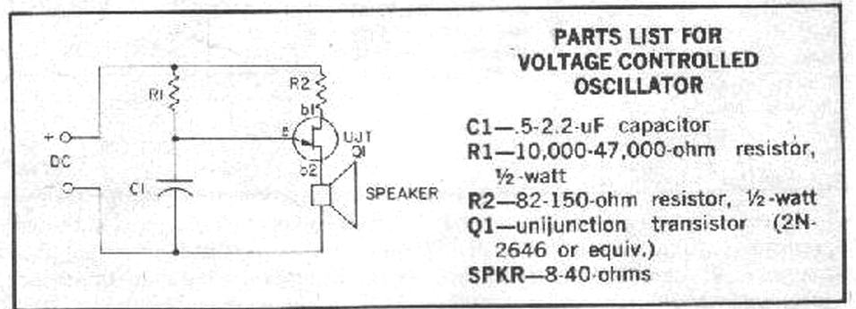
Unijunction transistors are very interesting. They love to be used in oscillators, and it doesn't take too many parts or very much coaxing to get their sawtooth outputs. This little squealer will tell you how much voltage it's connected...
This is a simple crystal tester circuit. The transistor T1 and the crystal form an oscillator. Capacitors C1 and C2 act as a voltage divider for the oscillator. If the crystal is functioning properly, the oscillator will operate effectively,...
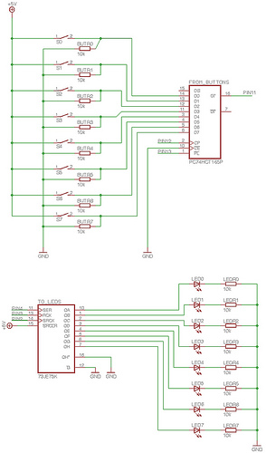
To enable the MonomeSerial software to recognize the monome clone, it is necessary to modify the Arduino's EEPROM serial number to match that of a genuine monome. Following Melka's updated instructions from the Bricktable blog is recommended. The D2XX...