
Common emitter amplifier circuit resistance and capacitance coupled basic

The common emitter amplifier circuit is a fundamental configuration in analog electronics, widely utilized for its ability to amplify voltage signals. This circuit employs a bipolar junction transistor (BJT) as the active component, where the emitter terminal is common to both the input and output circuits.
In this configuration, the input signal is applied between the base and emitter terminals, while the output is taken from the collector terminal. The use of resistors and capacitors in this circuit is crucial for establishing the desired operating point and frequency response.
Typically, the circuit includes a biasing network composed of resistors that set the DC operating point of the transistor, ensuring that it remains in the active region during operation. Capacitors are employed for coupling and bypassing purposes; coupling capacitors allow AC signals to pass while blocking DC components, and bypass capacitors enhance the gain by providing a low-impedance path to ground for AC signals at high frequencies.
The design parameters, such as resistor values and capacitor sizes, must be carefully selected based on the desired gain, input and output impedance, and frequency response. The common emitter amplifier is characterized by its high voltage gain, moderate input impedance, and low output impedance, making it suitable for various applications in audio and RF amplification.
In summary, the common emitter amplifier circuit, with its resistance and capacitance coupling, serves as a versatile and essential building block in electronic circuit design, providing effective signal amplification across a range of frequencies. Common emitter amplifier circuit resistance and capacitance coupled basic
Related Circuits
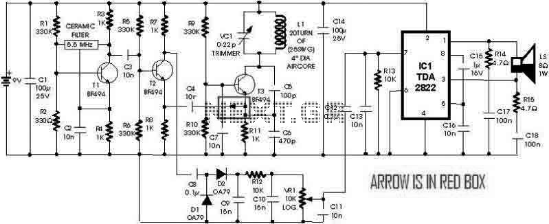
This is a simple metal detector utilizing a TDA2822 and several NPN transistors. An arrow indicates the signal flow direction from the Emitter of transistor T3 to the 10nF capacitor C4, which is opposite to the typical left-to-right flow...
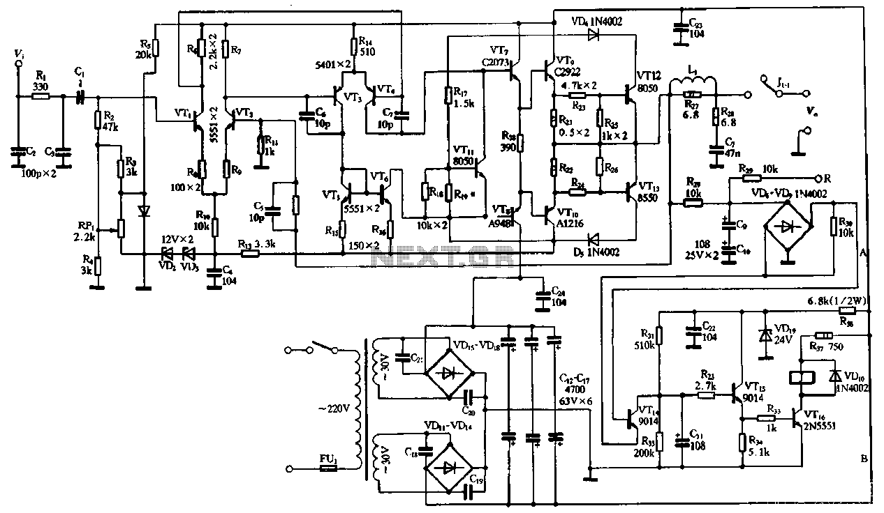
The performance of the amplifiers 2SC2922 and 2SA1216 (or 2SC3264 and 2SA1295) is excellent, featuring good linearity and strong overload capabilities. These devices are utilized as high-fidelity power amplifier stages, demonstrating outstanding performance. The circuit, as illustrated in Figure...
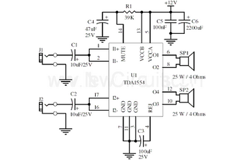
This document presents a 22-watt stereo audio power amplifier circuit diagram based on the TDA1554 integrated circuit from NXP Semiconductors (formerly Philips Semiconductors). The 22-watt stereo audio power amplifier circuit utilizing the TDA1554 IC is designed to deliver high-quality audio...
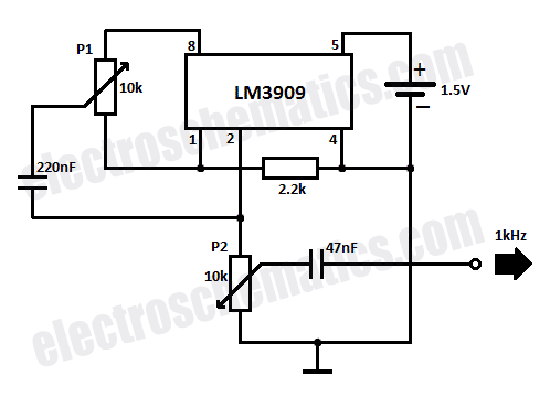
This circuit generates sine wave oscillations, but it can also be modified to produce triangle or square wave functions. The frequency is adjustable by varying the current. By disconnecting the 20k resistor (RIN) from the reference (REF) pin (pin...
This is a simple LED night light circuit that can serve as a room night lamp. The circuit is straightforward and can be constructed with a few components. It employs four LEDs to function as a night lamp. Users...
Last year, a low-cost tube stereo headphone amplifier kit from Oatley Electronics (located in New South Wales, Australia) was built and reviewed. This kit gained significant popularity and was sold globally. The headphone amplifier is based on new old...