
73 MHz Hallogene Radio-Controlled Lights

The described circuit utilizes a 73 MHz radio frequency to facilitate wireless control of halogen lights. The operation begins with the remote control, which is equipped with a push button switch. When the button is pressed, it sends a modulated signal at 73 MHz to the receiver circuit connected to the halogen lamp. The receiver circuit is designed to decode this signal and control the relay or transistor that manages the power supply to the lamp.
The circuit can be divided into two main sections: the transmitter (remote control) and the receiver (lamp control). The transmitter circuit consists of an oscillator that generates the 73 MHz carrier frequency. This signal is then modulated by the input from the push button, which may involve amplitude modulation (AM) or frequency modulation (FM), depending on the design.
The receiver circuit includes an RF receiver module tuned to 73 MHz, which captures the incoming signal. Upon receiving the modulated signal, the receiver demodulates it to retrieve the original control signal. This control signal is then processed to determine whether to activate or deactivate the relay or transistor that controls the power to the halogen lamp.
An important feature of the remote control is the LED indicator. This LED is connected in parallel with the push button and is activated when the button is pressed, providing visual feedback to the user that the signal has been transmitted.
Furthermore, the system may include additional components such as capacitors for filtering, resistors for biasing, and diodes for protection against voltage spikes. The design should ensure that the circuit operates reliably over the intended range of distances and that the power consumption is kept to a minimum to prolong battery life in the remote control.
In summary, this 73 MHz halogen radio-controlled light circuit effectively allows users to control the lighting remotely, providing convenience and ease of use through a simple push button interface.This circuit is 73 MHz Hallogene Radio-Controlled Lights. The purpose is to control the power state of a hallogene light by remote control. When we press the push of a remote control Botton, state lamp power will change, so, if the lamp is lit, it will be turned off and when lit, it will be turned off. If we press the button for another time, the same action will occur. When the button is pressed, the LED indicator lights on the remote control. This system consists of two separate circuits. One. 🔗 External reference
Related Circuits
This circuit provides an explanation of the Phase-Locked Loop (PLL) controller unit for an FM transmitter. It is crucial for maintaining a digitally controlled and stable transmitter frequency. The core component of this unit is a PIC processor, specifically...
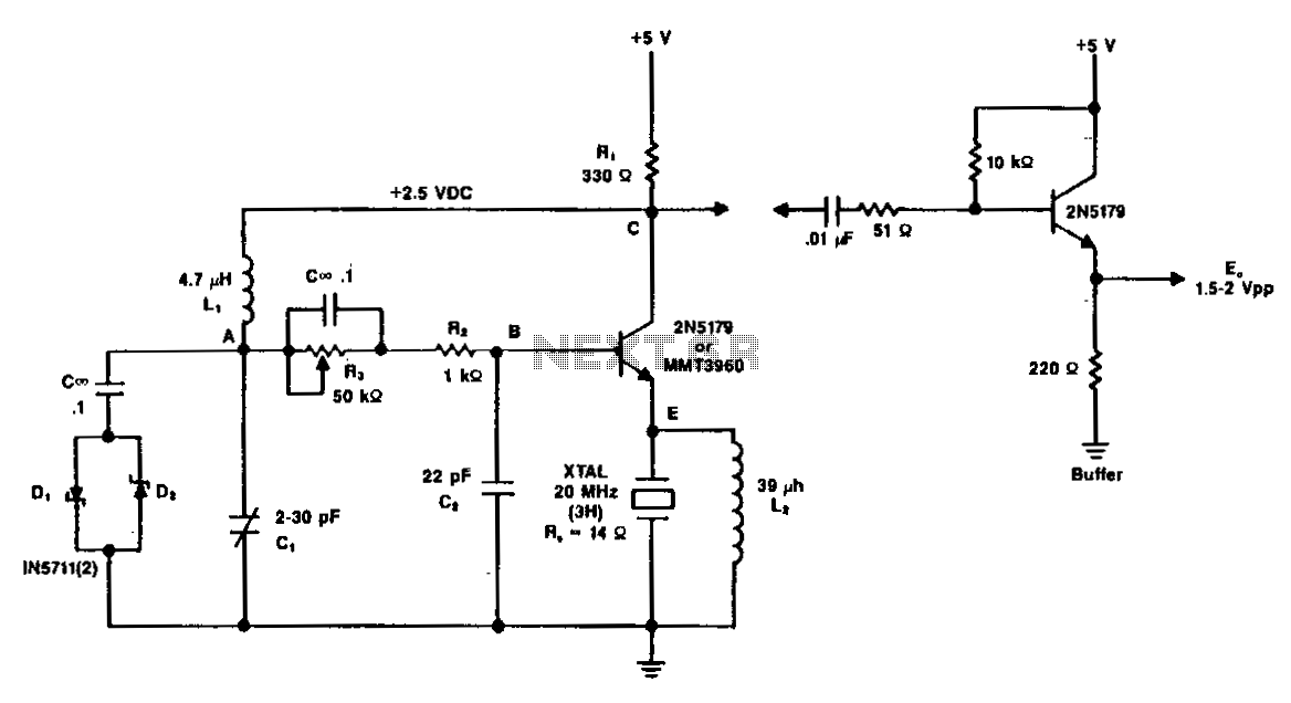
A typical circuit operating at 20 MHz is illustrated. The crystal, featuring an internal series resistance (Rs) of 14 ohms, oscillates at its third harmonic frequency. Diode clamps D1 and D2 ensure constant amplitude control. The transistor functions continuously...
This circuit generates a low power test signal and should not be used as a transmitter. Make sure you are within the law in the locality in which you operate this. As this was built from parts laying on...
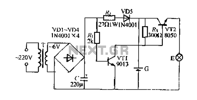
Figure 282 illustrates a simple emergency lamp circuit designed to activate during a power outage. The circuit utilizes a transformer (T) for voltage stepping, diodes (VD1 to VD4) for rectification, and a capacitor (C) for smoothing the output. During...

Most cars lack delayed interior lights. The presented circuit addresses this issue by gradually switching the interior lights on and off. This feature facilitates activities such as locating the ignition keyhole after the car door has been closed. The...
A water Happy Valley-type four flashing lights string controller, electric bollard is designed for use with a type J Ding Japanese lantern. The circuit employs a specific integrated circuit (IC) utilizing CMOS technology. It features a black soft cream...