
DTMF Multi-channel code decoding infrared remote control circuit

The infrared emission circuit in Figure (a) employs a 12-key keyboard to facilitate user input, where each key corresponds to a specific infrared signal generated by the S2559 infrared emitter. The S2559 is a compact, high-performance infrared emitter that operates efficiently within the designated wavelength range, ensuring reliable communication in various applications.
Figure (b) features the DTMF (Dual-Tone Multi-Frequency) decoder circuit, which is primarily based on the MT8870 integrated circuit. This circuit is designed to decode the dual-tone signals produced by the keypad input. The MT8870 processes the audio signals and converts them into digital signals, which can be used for further processing or control within the system. Additionally, the channel control circuit manages the routing of the decoded signals to the appropriate outputs, allowing for effective communication and control in telecommunication applications.
In Figure (c), the voltage amplifier circuit utilizes two LM358 operational amplifiers to amplify the input signal. The LM358 is a dual operational amplifier that provides high gain and bandwidth while maintaining low power consumption. This circuit configuration allows for a significant increase in signal strength, making it suitable for applications that require precise signal amplification. The use of two op-amps enables differential amplification, which can help reduce noise and improve overall signal integrity.
Overall, these three figures represent essential components of a comprehensive electronic system, integrating user input, signal decoding, and amplification to achieve effective communication and control.Figure (a) is the infrared emission circuit that composed of 12 the keyboard and S2559. Figure (b)shows DTMF decoder circuit and channel control circuit composedof the MT8870. Figure (c) is the voltage amplifier circuit composed of two-op ampLM358.. 🔗 External reference
Related Circuits
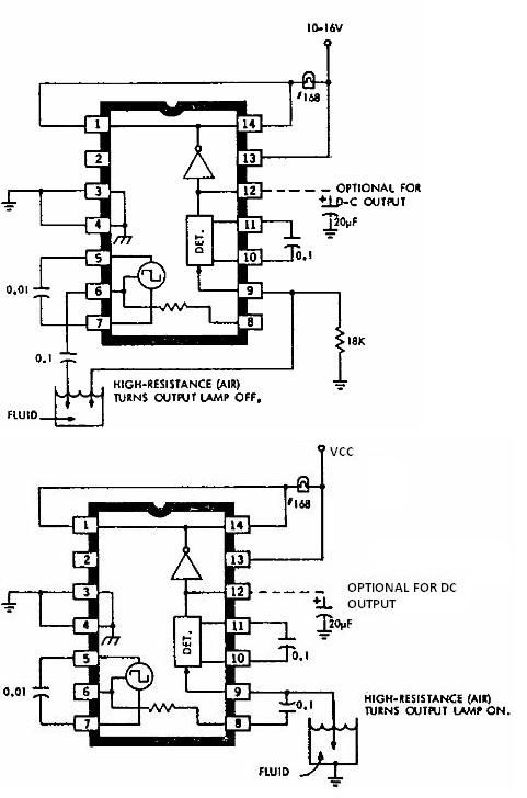
This electronic liquid detector circuit diagram is based on the ULN2429 monolithic bipolar integrated circuit designed for detecting the absence or presence of many different types of liquids. The ULN2429 electronic liquid detector circuit can be used in automotive,...
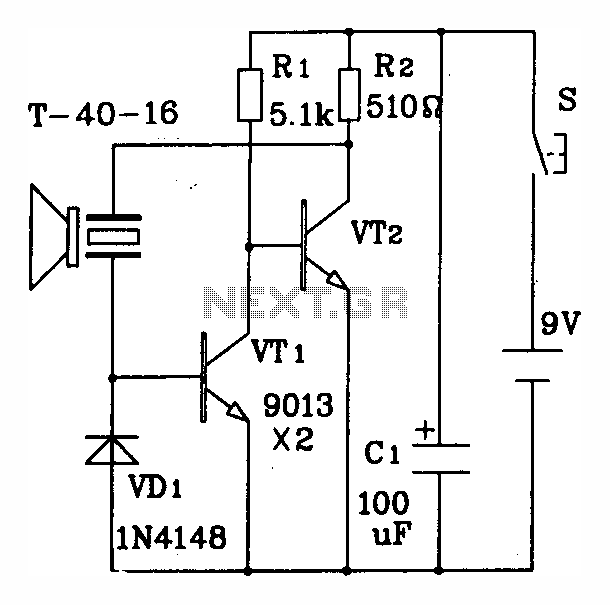
The discrete components ultrasonic transmitting circuit T/R-40-16 is capable of emitting a series of ultrasonic signals at a frequency of 40 kHz. This circuit operates at a voltage of 9V, with an operating current of 25 mA, and can...

The schematic for this tutorial is illustrated below and includes all necessary components for the tutorial to function. The PIC programming circuitry is not included, as it is assumed that the PIC is either programmed externally or that the...

The MP3302 is a boost converter integrated circuit (IC) specifically designed for LED drive applications. It is capable of driving 27 LEDs, arranged as 9 strings of 3 white LEDs in series, powered by a lithium-ion battery. The IC...
This TDA2030 35-watt audio amplifier circuit project is designed to deliver an output power of 35 watts into an 8-ohm load. The TDA2030 is a monolithic integrated circuit housed in a Pentawatt package, intended for use as a low-frequency...
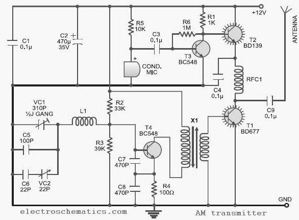
This low-cost AM transmitter is tunable from 10 to 15 MHz with the assistance of a ½J gang condenser VC1, which sets the carrier frequency of the amplitude modulation transmitter in conjunction with inductor L1. Frequency trimming can be...