
75 impedance RF2320 linear amplification circuit diagram

The impedance linear amplifier circuit designed with the RF2320 is intended for applications requiring high fidelity and low distortion signal amplification. This circuit is particularly suitable for radio frequency (RF) applications where maintaining the integrity of the signal is crucial. The RF2320 is a versatile amplifier capable of providing a wide bandwidth and is optimized for 75-ohm systems, making it ideal for television and cable applications.
The circuit's layout typically includes two 75-ohm connectors, J1 and J2, which serve as the input and output ports, respectively. These connectors ensure that the amplifier is properly matched to the characteristic impedance of the transmission line, minimizing reflections and maximizing power transfer.
In operation, the RF2320 amplifies the input signal while maintaining a linear response across the desired frequency range. The design may include additional components such as resistors and capacitors to stabilize the amplifier, filter out unwanted frequencies, and enhance overall performance. Careful attention must be paid to the power supply and grounding arrangements to prevent noise and ensure optimal operation.
Overall, this impedance linear amplifier circuit is a critical component in RF signal processing, providing robust amplification while adhering to the necessary impedance standards for effective transmission and reception of signals. As shown in FIG 75 impedance linear amplifier circuit configured by RF2320. J1 and J2 are 75 F connector.
Related Circuits
The LM1830 fluid level detector circuit is a device designed to indicate the presence or absence of aqueous solutions. It features a low external parts count, a wide operating supply range, an internally regulated supply, and AC or DC...
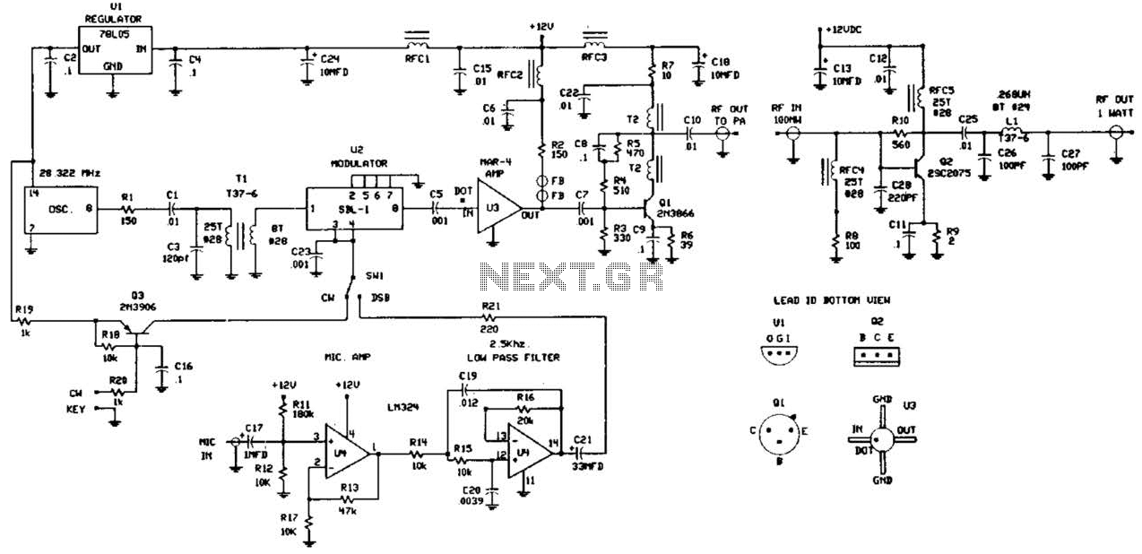
This circuit was detailed in a recent edition of an amateur radio magazine. It enables operation in the 160 to 190 kHz band with a maximum power output of 1 W (license-free) in various modes such as CW, SSB,...
This power supply was designed for use with the Simple hybrid amplifier published elsewhere in this issue. It is suitable for various applications as well. A cascade generator is utilized for the 170 V output, a switch-mode supply provides...
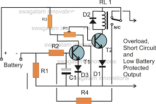
The battery voltage must pass through resistor R1 before reaching the output load. As a result, the current flowing through R1 is proportionately transformed into a voltage across it. When the battery voltage drops below a certain threshold, the...
This is a complete alarm system with five independent zones suitable for a small office or home environment. It utilizes three CM integrated circuits and features a timed entry/exit zone, four immediate zones, and a panic button. There are...
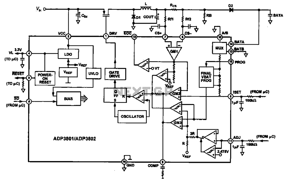
Charging circuit diagram for personal work based on the operating principle of ADP3801/3802 charging circuit. The ADP3801/3802 is a highly integrated battery charger controller designed for Li-ion and Li-polymer batteries. The charging circuit typically consists of several key components including...