
Low Battery Cut off and Overload Protection Circuit

The described circuit operates as a voltage monitoring and control system. The primary component, R1, serves as a current-limiting resistor that influences the voltage drop across itself based on the current flowing through it. This voltage drop is critical for regulating the operation of transistor T2, which functions as a switch for the relay controlling the load.
When the battery voltage is at an acceptable level, the current through R1 produces a sufficient base current for T2, allowing it to remain in the 'ON' state. In this state, T2 activates the relay, completing the circuit to the load and enabling its operation. However, as the battery voltage declines and crosses a predetermined threshold, the base current of T2 diminishes. This reduction leads to T2 transitioning to the 'OFF' state, which interrupts the current flow to the relay and consequently disconnects the load.
The design ensures that the load is only powered when the battery voltage is above the critical threshold, thereby preventing potential damage to the load from insufficient voltage conditions. This circuit is particularly useful in battery-powered applications where load protection and power management are essential for prolonging battery life and ensuring reliable operation. Proper selection of R1 and the characteristics of T2 are crucial for achieving the desired voltage threshold and response time in this monitoring system.The battery voltage has to pass through R1 before reaching the load at the output and therefore the current passing through it is proportionately transformed into voltage across it. When the battery voltage falls beyond a certain low voltage threshold, the base current of T2 becomes sufficiently low such that its no longer able to hold the relay i
nto conduction and switches it OFF and also the load. 🔗 External reference
Related Circuits
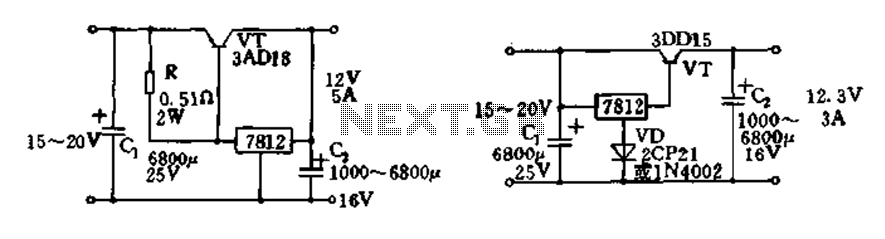
Expand integrated three-terminal regulator block circuit output current method The integrated three-terminal regulator is a versatile component commonly used in power supply circuits to provide a stable output voltage. This regulator typically consists of three terminals: input, output, and ground....
This circuit functions with inaudible (ultrasonic) sound. Sound of frequency up to 20 kHz is audible to human beings. The sound of frequency above 20 kHz is called ultrasonic sound. The circuit described generates (transmits) ultrasonic sound of frequency...
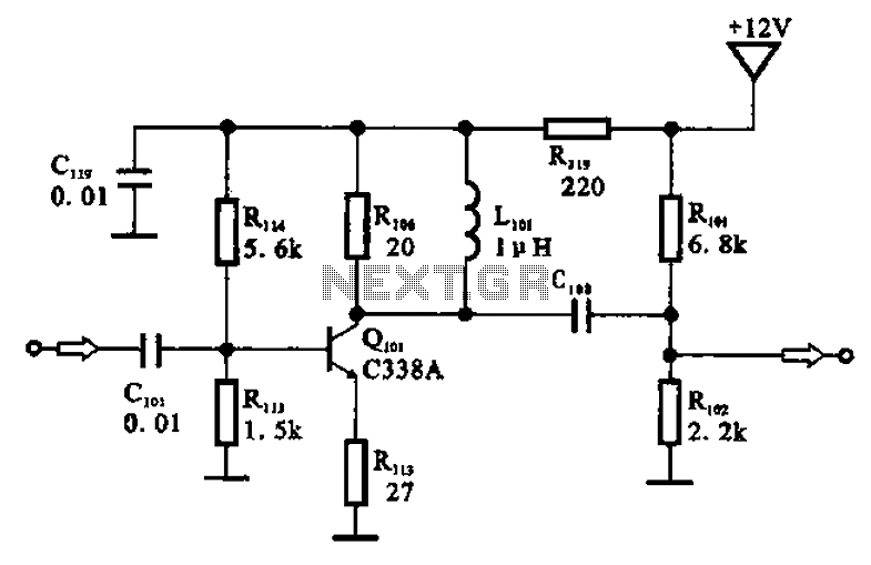
The amplifier circuit is designed as a pre-amplifier configuration. It utilizes transistor Q101 and other components such as inductor L101 and biasing elements. The transistor operates as a common emitter intermediate frequency (IF) amplifier. The IF signal is coupled...

Dual power for each load refers to the operation of two power supplies working simultaneously to handle the electrical load. In the event of a power outage, a contact switch automatically closes all load circuits that are not powered...
This page is provided to the domain owner free of charge by Sedo's Domain Parking. The domain owner and Sedo do not have any relationship with third-party advertisers. References to any specific service or trademark are not controlled by...
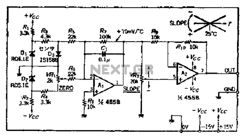
A temperature sensor can be created using a standard silicon diode, which produces approximately 2.2 mV per degree Celsius variation. An operational amplifier (OP amplifier) is utilized with a positive reference temperature (room temperature). The output signal is amplified...