
78xx Voltage Regulators

The 78xx series voltage regulators are linear voltage regulators that provide a stable output voltage from a higher input voltage. They are available in various fixed output voltages such as 5V, 12V, and 15V, making them versatile for different applications. The input voltage must be higher than the desired output voltage by a certain margin, known as the dropout voltage, which is typically around 2V for these regulators.
The circuit configuration typically includes the voltage regulator IC, input and output capacitors (C1, C2, and C3), and sometimes an additional electrolytic capacitor (C4) for improved transient response. The input capacitor (C1) is essential for filtering the input voltage and reducing ripple, while the output capacitor (C3) enhances stability and transient response. The placement of these capacitors is critical; they should be located as close to the regulator pins as possible to minimize inductive effects and ensure effective decoupling.
Thermal management is crucial for the reliable operation of the 78xx regulators. The use of heatsinks can significantly improve thermal performance, especially in applications where high current loads are expected. The thermal resistance of the heatsink must be considered to ensure that the junction temperature of the IC remains within safe limits.
In summary, the 78xx series voltage regulators are straightforward to implement in analog power supply designs, requiring minimal external components while providing robust voltage regulation. Proper selection and placement of capacitors, along with adequate thermal management, are essential for optimal performance and reliability of the circuit.The voltage regulators from the 78xx-series are found in many analogue power supplies. It seems, then, somewhat super‚uous to say much more about them. But on the other hand, it can be very useful to highlight the important points, just because they are so ubiquitous. The 78xx is almost always used bare`, because additional components are almost unnecessary. In fact, only one additional component is required, and that is capacitor C2. Based on the manufacturer`s recommendation, this capacitor should be 220nF in order to prevent oscillatory behavior. In practice, you will almost always see that a 100nF capacitor used here. This is a value that does not cause problems. C1 is the smoothing (reservoir) capacitor, its purpose is to reduce the ripple of the rectified AC voltage and is not actually related to voltage regulation.
If the DC voltage is provided by a mains adapter, then this electrolytic capacitor is usually already part of the adapter, although the value is rather small sometimes. C2 may only be omitted if C1 is close to the 78xx and C1 is of good quality (low ESR). But there is nothing wrong by playing it safe and alwaystting C2. Rule of thumb: always place a 100 nF capacitor on the input as close to the regulator as is practicable.
Strictly speaking, there is no need for a capacitor on the output. However, a capacitor of at least 100 nF (C3) ensures much-improved regulation with fast (several microseconds) changes in load current. In practice, a decoupling-capacitor is placed close to the power supply pins of many ICs. These can provide the same function, provided they are placed not too far away. An electrolytic capacitor (C4) can be added for similar reasons: to catch slow (and fast, if it is a good capacitor) variations in load current.
There is actually no compelling reason to deal with slow variations, because the IC is fast enough of regulating these on its own. Rule of thumb: always place an output capacitor of at least 100 nF preferably as close as possible to the IC with the greatest current consumption (read: greatest changes in current consumption).
When building the circuit, it is important to connect the capacitors via the shortest possible path. So don`t use long wires or make large loops. Obtain the input voltage for the regulator directly from the connections of the smoothing capacitor, because the ripple is smallest there. Finally, a few remarks about the temperature that a 78xx may run at. As arst approximation, if seem to burn yourngers when touching the regulator, the temperature of the regulator is above 60 °C and a (small) heatsink is definitely recommended.
It is not really a problem when the IC gets too hot, because it was designed in such a way that it will turn itself off when the temperature is too high. It doesn`t actually turn off, but the output current reduces when the temperature increases. When the internal temperature has reached 150 °C, the output current will be only a little more than half the current delivered at 25 °C.
That is why it is possible that the output voltage of the regulator has dropped even though the output current is less than the rated current for the IC. A heatsink is the obvious solution. Rule of thumb: you should be able to touch the regulator (or the heatsink) without burning yourself. If not, then the heatsink has to be larger. 🔗 External reference
Related Circuits
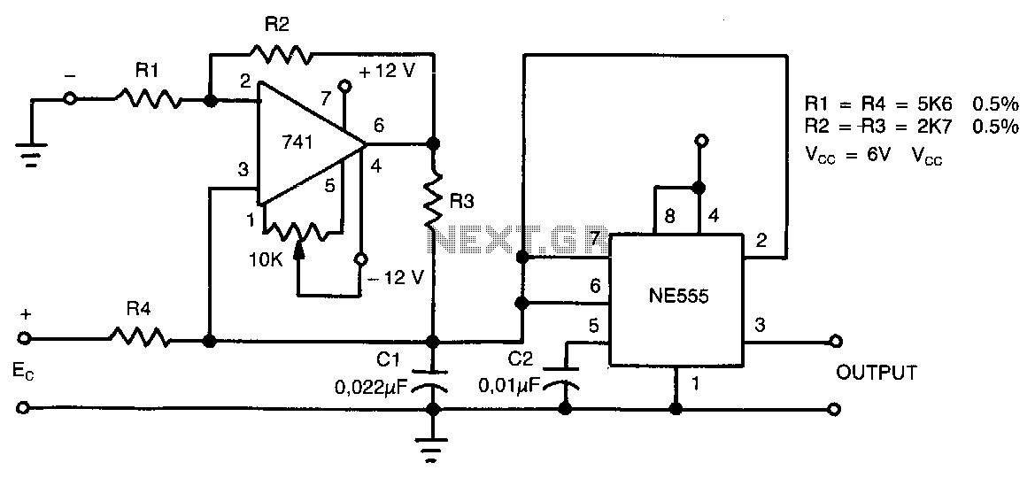
This circuit can accept positive, negative, or differential control voltages. The output frequency is zero when the control voltage is zero. The 741 operational amplifier forms a current source controlled by the voltage Ec to charge the timing capacitor...
The linearity of the input sweep voltage in relation to the output frequency is significantly enhanced by utilizing an operational amplifier. The utilization of an operational amplifier (op-amp) in electronic circuits is a common practice to improve the linearity of...
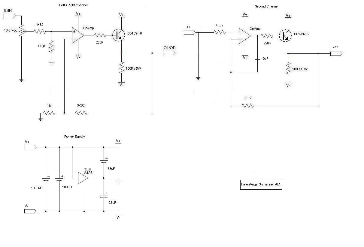
The schematic shows R4 at the emitter of the transistor, as suggested by Amb and Majkel. It should be positioned between the operational amplifier and the transistor, which is also the correct configuration in the CanAmp. The amplifier observed...
When the input voltage is 0 the LED glows. The LED stops glowing when the voltage rises to the level determined by R2. Reverse + and - pins to reverse operating mode. To set voltage at which LED goes...
This device generates high-voltage pulses that disrupt muscles and the nervous system, causing mental confusion in anyone who comes into contact with it. It can be utilized against aggressive animals or attackers; however, it is important to note that...
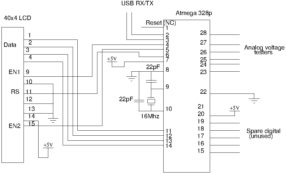
Drive a four-line LCD panel using an Arduino. The project initially aimed to control the LCD for displaying arbitrary information but evolved to include functionalities such as timekeeping, EEPROM read/write operations from the Atmel 328p, and voltage measurement. Multiple...