LED Speedometer circuit
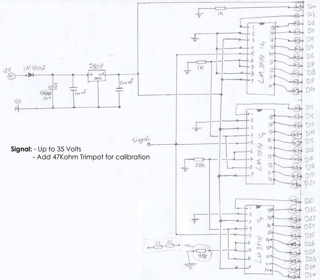
The circuit schematics operate at 12 Volts, sourced from a car battery. The ground connection is tied to the car chassis, while the signal is received from a sensor connected to a stepper motor. The No. 5 pin of the LM3914 is utilized.
The circuit described employs the LM3914, a voltage level indicator that can display the input voltage across multiple LEDs. In this application, the LM3914 is configured to visualize the signal received from a sensor connected to a stepper motor, which may serve a variety of functions such as position feedback or speed monitoring.
The power supply for the circuit is derived from a standard 12 Volt car battery, ensuring compatibility with automotive applications. The ground connection is established through the car chassis, providing a stable reference point for the circuit operation.
The sensor output, which is connected to the LM3914, is likely an analog voltage that varies based on the position or speed of the stepper motor. The LM3914 can be configured in either dot mode or bar mode, allowing for flexible visual representation of the input signal. The No. 5 pin of the LM3914 is particularly important as it typically corresponds to the output of the fifth LED in the sequence, which can indicate a specific threshold or level of the input signal.
This circuit may also include additional components such as resistors to limit current to the LEDs, capacitors for noise filtering, and possibly a potentiometer for calibrating the sensitivity of the sensor input. Proper layout and design considerations should be taken into account to minimize interference and ensure reliable operation within the automotive environment.Attached the circuit schematics 12 Volts : from car battery Ground : Car chassis Signal : from the sensor stepper motor The No 5 Pin of LM3914 c.. 🔗 External reference
