
8 Channel LPT Relay Circuit

The circuit design incorporates a Power Battery Terminal (PBT) to streamline the connection of relays and auxiliary power sources, enhancing the overall functionality and ease of use. Each relay channel is equipped with an LED indicator that visually represents the operational status of the relay, allowing for quick diagnostics and monitoring.
The use of Berg pins for power and trigger voltage connections simplifies the wiring process, enabling users to efficiently connect and disconnect components as needed. This modular approach not only improves the reliability of the connections but also facilitates maintenance and troubleshooting.
The relay output can be utilized for various applications, including controlling high-power devices or interfacing with other electronic systems. The design ensures that the relays are activated only when the appropriate trigger voltage is applied, thereby protecting the circuit from accidental activation.
Overall, this circuit exemplifies a practical solution for managing relay outputs and auxiliary power connections, making it suitable for a wide range of electronic projects and applications.This circuit is using Power Battery Terminal (PBT) for easy relay output and aux power connection. The LED on each channel indicates relay status. Berg pins for connecting power and trigger voltage. 🔗 External reference
Related Circuits
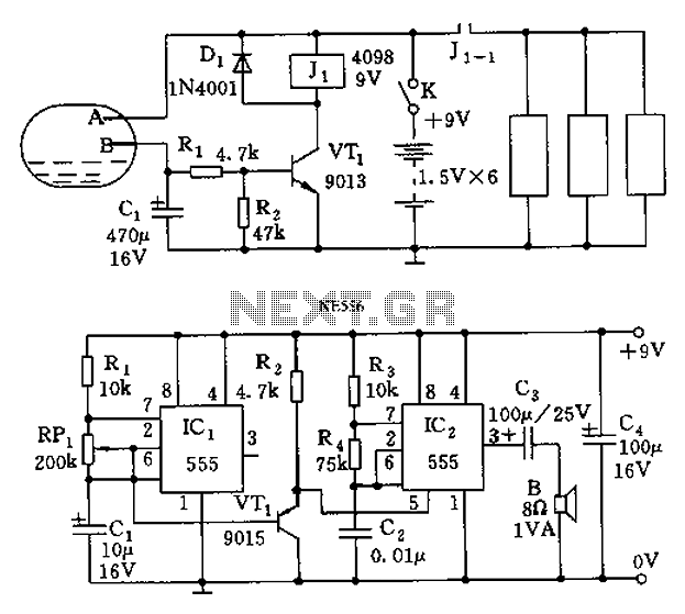
The call is triggered by the position sensing circuit, which activates the control circuit and SOS alarm circuit. This system is designed for critically ill patients or to assist disabled individuals in the event of a fall. A position...
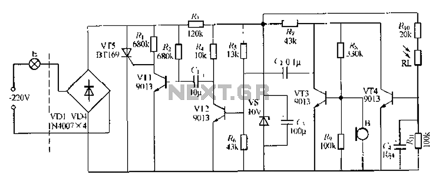
This circuit describes a sound and light control delay system for a walkway stairs light switch. It involves various components including 220V AC electric bulbs, diodes (VD1-VD4), and resistors. The circuit utilizes a rectifier regulator to stabilize the voltage...
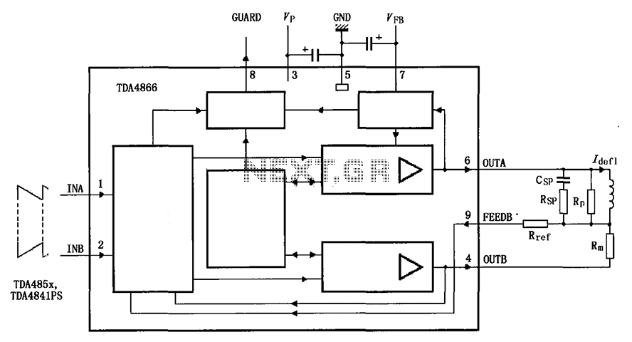
The TDA4866 is a 90-color power amplifier designed for vertical deflection systems, operating at a frequency range of 50 to 160 Hz. The CRMM circuit is implemented to ensure a high current drive input. The amplifier features a dual...
This inverter is very easy to construct, reliable, and even powerful enough to light up a 15W fluorescent tube (if you cool your transistor well). The only hard-to-find piece of this baby is the so-called yellow inverter transformer. It's...
This design is for an interpolating scanner, a circuit featuring multiple signal inputs, a control voltage input, and a signal output. The output selectively transitions between inputs, smoothly fading from one to the next as the control voltage increases....
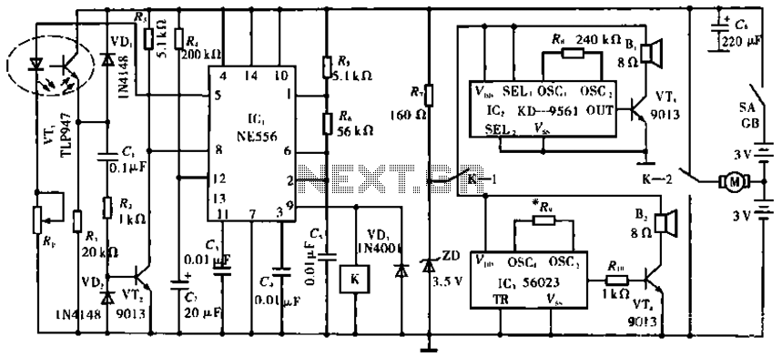
The circuit operates with VT1, which is an integrated infrared receiver, utilizing a red-emitting diode for perimeter triode reception. IC1 (NE556) functions as a dual timer, with R5, R6, and C5 forming an oscillation circuit that generates a frequency...