
555 fall means a circuit diagram for help

The electronic schematic described involves multiple circuits working in tandem to ensure rapid response in emergencies. The position sensing circuit utilizes a mercury switch to detect a fall. This switch is designed to close the circuit when the sensor is tilted beyond a certain angle, indicating a fall. The circuit includes two main contacts, A and B, which become conductive when the mercury flows to complete the circuit.
Upon activation, the circuit charges capacitor C1, which is part of an astable multivibrator configuration. This multivibrator is critical for generating a consistent oscillation period, set to approximately one second, allowing for a reliable timing mechanism that can be used to generate repeated signals. The charging and discharging of C1 create a triangular waveform, which is essential for the next stage of the circuit.
The output from the astable multivibrator is fed into a transistor (VT1), which acts as a switch to control the power supply to the alarm system. When VT1 is activated, it pulls the relay (J1), which connects the power supply to the sound-emitting device. This device is designed to produce a loud sound to alert others for help.
The second stage of the circuit involves IC2, a controllable multivibrator that takes the output from the astable multivibrator. This IC is designed to modulate the control voltage based on the input it receives, allowing it to generate sounds that mimic an ambulance siren. This feature is particularly useful in emergency situations, as it can attract immediate attention.
Overall, the system is a critical tool for ensuring the safety of individuals who may be at risk of falling, providing a reliable means of alerting caregivers or emergency responders. The integration of position sensing, timing circuits, and sound generation in a compact design makes it an effective solution for fall detection and emergency signaling. As shown, the call falls by the position sensing circuit trigger control circuit and SOS alarm circuit. For critically ill patients or for help with a disabled person falls. Pa tients with chest pocket position sensor placed inside the box with a mercury switch, horizontal. When the fall, A, B two contacts are electrically conductive mercury ON, C1 immediately charged, VT1 conduction, J1 pull, the power supply circuit is turned on the sound, so the sound rang for help. IC1 and R1, RP1, C1 composition astable multivibrator oscillation period transferred to T 1 second. Charging and discharging the capacitor C1 to form a triangular wave VT1, the emitter follower output added to the controllable multivibrator IC2, the IC2 with the change in control voltage issued a similar message called an ambulance sound.
Related Circuits
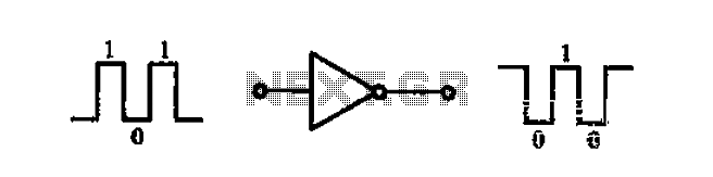
A common-emitter transistor amplifier produces an output signal that is 180 degrees out of phase with the input signal, commonly referred to as an inverting amplifier. When the electrical path for amplifying the pulse signal is activated, this circuit...

Referring to the simplified schematic in A, the audio frequency generator (AFG) consists of 10 relatively simple circuit elements. IC1-c and IC1-d are configured as unity-gain non-inverting buffer amplifiers. The summing amplifier, IC2-c, combines equal amounts of the left...

This document provides a circuit diagram of a car stereo. It includes a circuit diagram of a Class B 15 Watts audio amplifier designed using a dual op-amp and a transistor. The 15 W Class B audio amplifier circuit...
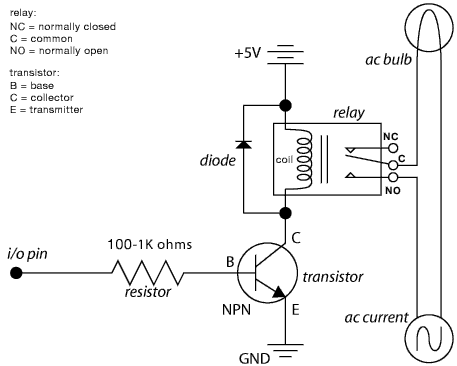
The schematic illustrates the Relay Wiring Circuit Diagram used to control an air conditioner or other high-current devices via a microcontroller. The relay wiring circuit serves as an interface between low-voltage microcontroller signals and high-voltage appliances, such as air conditioners....

This compact single-chip circuit is designed for measuring the level of electrically conductive fluids or liquids. It functions as a voltage level sensor and employs an AC bias supply to prevent electrolysis of the probes, thereby enhancing their lifespan....

The drain-to-source resistance of Q1 varies depending on the acidity of the sample presented to Q1's gate circuit. This variable resistance influences the current flowing through the bridge, which is proportional to pH. The circuit involves a field-effect transistor (FET),...