
Toy police car circuit

The described circuit employs a combination of an infrared emitting diode and an integrated infrared receiver to facilitate remote sensing applications. The NE556 integrated circuit serves as the timing element, configured to produce a square wave output at a frequency of around 1,200 Hz. This oscillation is critical for modulating the infrared light emitted by the diode, allowing for effective communication or sensing over a specified distance.
The infrared emitter, driven by the oscillation from the NE556, generates pulses of infrared light that can be detected by the infrared receiver circuit. The receiver, consisting of the infrared receiver diode and additional passive components (R1, C1, R2), is responsible for detecting these modulated signals. The photoelectric conversion process converts the received infrared light pulses into electrical signals, which are then processed by the pulse trigger circuit formed by VT2.
The overall design is suitable for applications such as remote control systems, motion detection, or any scenario requiring non-contact sensing. The use of modulation in the infrared light helps minimize interference from ambient light sources, enhancing the reliability of the system. The choice of components, including the NE556 timer and the specific resistor and capacitor values, allows for precise control over the timing and frequency characteristics of the circuit, making it adaptable for various operational requirements.Circuit works: VT1 is integrated infrared receiver, the red-emitting diode Xiao perimeter triode reception. IC1 (NE556) is a dual time base manifold by R5, R6, C5, composed of an oscillation circuit, the oscillation frequency is about 1 200 Hz, by 5 feet to
drive the infrared emitting diode emits modulated infrared light. Infrared receiver diode R1, C1, R2, VT2 composition infrared receiver, photoelectric conversion and pulse trigger circuit.
Related Circuits
The LME49810 audio amplifier schematic is depicted in the accompanying circuit diagram. Based on the LME49810 datasheet, this component is a high-fidelity audio power amplifier driver intended for use in applications such as audio-video receivers, guitar amplifiers, powered studio...
A problem has been encountered in a Phase-Locked Loop (PLL). A loop filter has been utilized, but the output spectrum does not meet expectations. In a Phase-Locked Loop (PLL) system, the loop filter plays a crucial role in determining the...

The TPS61200 specifications indicate that GND serves as the control/logic ground, while PGND is designated as the power ground. However, this distinction is not accurately represented in the symbols used in the diagram. There is also confusion regarding the...
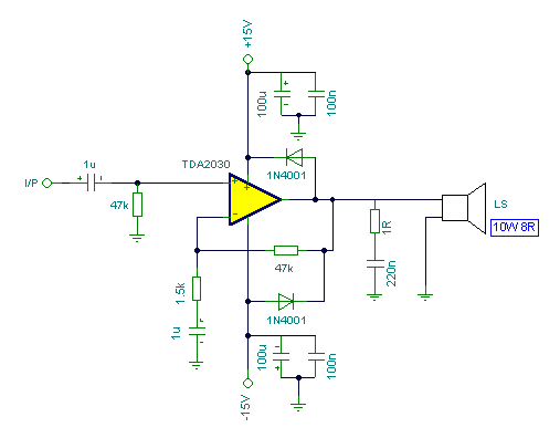
Connecting two TDA2030 through inexpensive power transistors allows for the creation of an amplifier capable of delivering higher power. This can be achieved by utilizing the component values specified in the schematic. To implement this circuit, two TDA2030 integrated circuits...
Both circuits can synchronize trapezoidal wave voltage, which is converted into intermittent small rectangular pulses. Its working principle involves periodic operation in synchronization with the grid frequency of the zero-volt switching voltage of the DC chopper. Due to the...
The circuit presented is a standard Colpitts oscillator, commonly utilized in many amateur radio homebrew transmitters. This specific circuit is designed to operate effectively within a frequency range of 1500 kHz to 8000 kHz. To accommodate lower frequencies, it...