
8 Led Audio VU Meter

The audio level meter circuit employs two LM324 quad op-amps configured as a comparator to detect varying audio levels. The circuit is designed to illuminate a series of eight LEDs, each corresponding to a different range of audio signal levels. The LM324 is chosen for its versatility and availability, making it a suitable choice for various audio applications.
In operation, the audio input signal is fed into the non-inverting inputs of the op-amps. Each op-amp is connected to a reference voltage set by a voltage divider, which is typically derived from the circuit's power supply. The output of each op-amp drives a corresponding LED through current-limiting resistors, which in this case are specified as 1K ohms. These resistors are critical in determining the threshold levels at which the LEDs will activate.
The choice of 1K resistors allows for a balanced response across the audio levels, ensuring that each LED lights up at progressively higher input signals. If higher resistance values, such as 5K ohms or more, are used, the circuit's sensitivity may diminish, potentially preventing some LEDs from activating, particularly at lower audio levels.
The op-amps' gain settings can be adjusted to fine-tune the circuit's response to the audio signal, allowing for customization based on specific application requirements. For enhanced performance, bypass capacitors may be added to the power supply pins of the op-amps to mitigate noise and improve stability.
This audio level meter circuit can be utilized in various applications, including audio mixing consoles, sound level monitoring, and visual sound representation in musical equipment. The simplicity and effectiveness of this design make it a popular choice for both hobbyists and professionals in the audio engineering field.This circuit uses two quad op-amps to form an eight LED audio level meter. The op-amp used in this particular circuit is the LM324. It is a popular IC and should be available from many parts stores. The 1K resistors in the circuit are essential so that the LED`s turn on at different audio levels. There is no reason why you can`t change these resistors, although anything above 5K may cause some of the LED`s to never switch on. This circ 🔗 External reference
Related Circuits
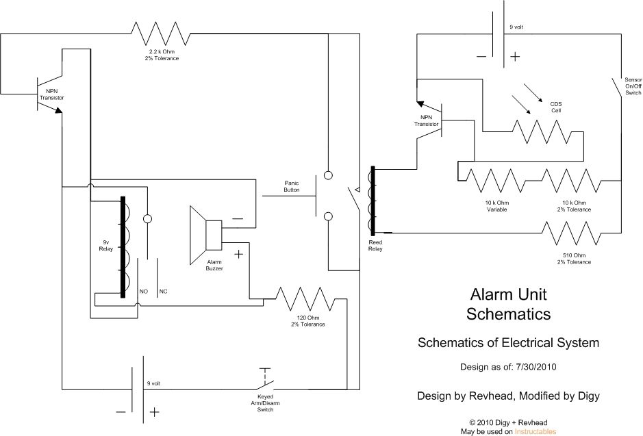
Learn how to strengthen your security system, regardless of its size, with this innovative and customizable laser grid. Once an individual crosses the threshold, the system activates... The concept of a customizable laser grid for security applications involves the deployment...
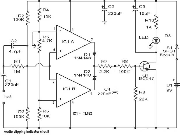
Clipping is a significant issue that leads to distortion in amplifiers. It results in the amplitude level of a waveform dropping abruptly before it reaches its intended limit. This document presents a straightforward circuit designed to detect clipping in...
The project involves displaying the current room temperature using an LM35 temperature sensor. This schematic differs from a previous schematic that utilized a multiplexed seven-segment display. In the earlier schematic, the display select I/O pins were RA0, RA1, RA2,...

A single preset resistor is utilized across all measurement ranges, which simplifies the setup process. Diode clamping is incorporated to protect the meter from damage if the unknown resistor exceeds the selected range. When the meter is assembled, a...
This solid-state push-pull single-ended Class A circuit is capable of providing sound quality comparable to that of valve amplifiers. It delivers an output power of 6.9W when measured across an 8 Ohm loudspeaker cabinet load, with reduced total harmonic...
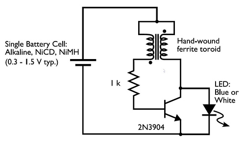
In the circuit diagram for the Joule Thief, the common point of the toroid is the connection at the top of the hand-wound ferrite toroid, located in the upper right of the diagram. This connection leads to the positive...