
Thermometer with PIC Microcontroller

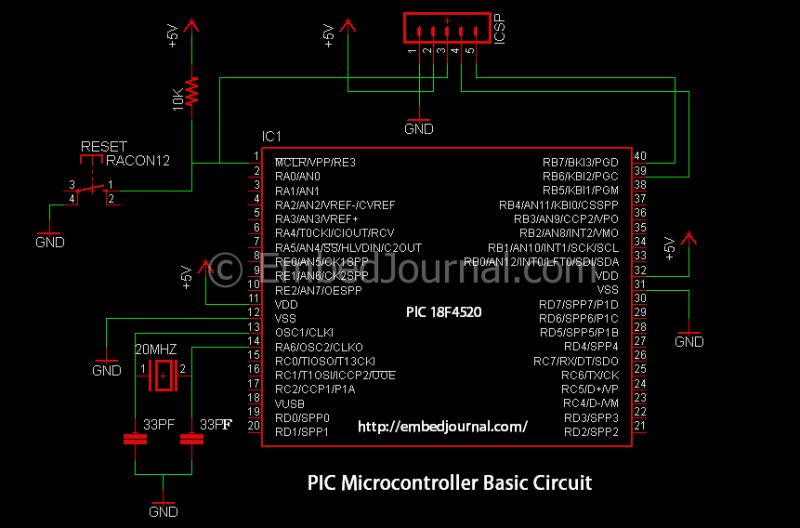
The schematic for this project integrates an LM35 temperature sensor, which outputs a voltage proportional to the temperature in degrees Celsius. The LM35 connects to the PIC microcontroller via one of its analog input pins, specifically RA0, which reads the output voltage from the sensor. The ADC of the PIC18FXXXX series MCU converts this analog voltage to a digital value, which can then be processed to determine the temperature.
The display mechanism employs a multiplexed seven-segment display controlled by the microcontroller. In this configuration, the display lines are connected to the I/O pins RA1 through RA4. The multiplexing technique allows for efficient use of the microcontroller's pins, enabling the display of numerical values representing the temperature without requiring an excessive number of pins. The program running on the microcontroller continuously reads the temperature data from the LM35, processes it, and updates the display accordingly.
The PIC Development Board serves as the foundation for this project, providing power and necessary interfaces for the microcontroller and peripheral components. The expansion board allows for easy integration of the LM35 and the display module, facilitating a seamless development process. Overall, this setup efficiently demonstrates the capability of the PIC microcontroller to interface with analog sensors and drive a display for real-time temperature monitoring.We will use them to show current room temperature using a LM35 temperature sensor. Please note that this schematic is slightly different from our previous schematic on multiplexed seven segment display. The display select i/o pins were RA0, RA1, RA2, RA3 on that schematic. But in this schematic the display lines are RA1, RA2, RA3, RA4 this is because RA0 is used as analog input channel for LM35`s output. We use our PIC Development Board for making the above demo project. The PIC Development Board has all the core circuitry to sustain the MCU while the project specific part is developed on the expansion board. /* LM35 Temperature Sensor INTERFACING TEST PROGRAM - Simple Program to connect with LM temperature sensor using the internal ADC of PIC MCU.
The program displays the current environment temperature on LED Module. MCU: PIC18FXXXX Series from Microchip. Compiler: HI-TECH C Compiler for PIC18 MCUs 🔗 External reference
Related Circuits

The reflected infrared (IR) signal detected by the photodiode is sent to a signal conditioning circuit, which filters out unwanted signals and amplifies the desired output. The circuit begins with a photodiode that captures the reflected IR signals. The photodiode...
Connect any I2C client chip (such as temperature sensors, analog-to-digital converters, displays, or relay drivers) to your PC via USB quickly, easily, and affordably. Drivers are available for both Linux and Windows operating systems. The described system facilitates the integration...
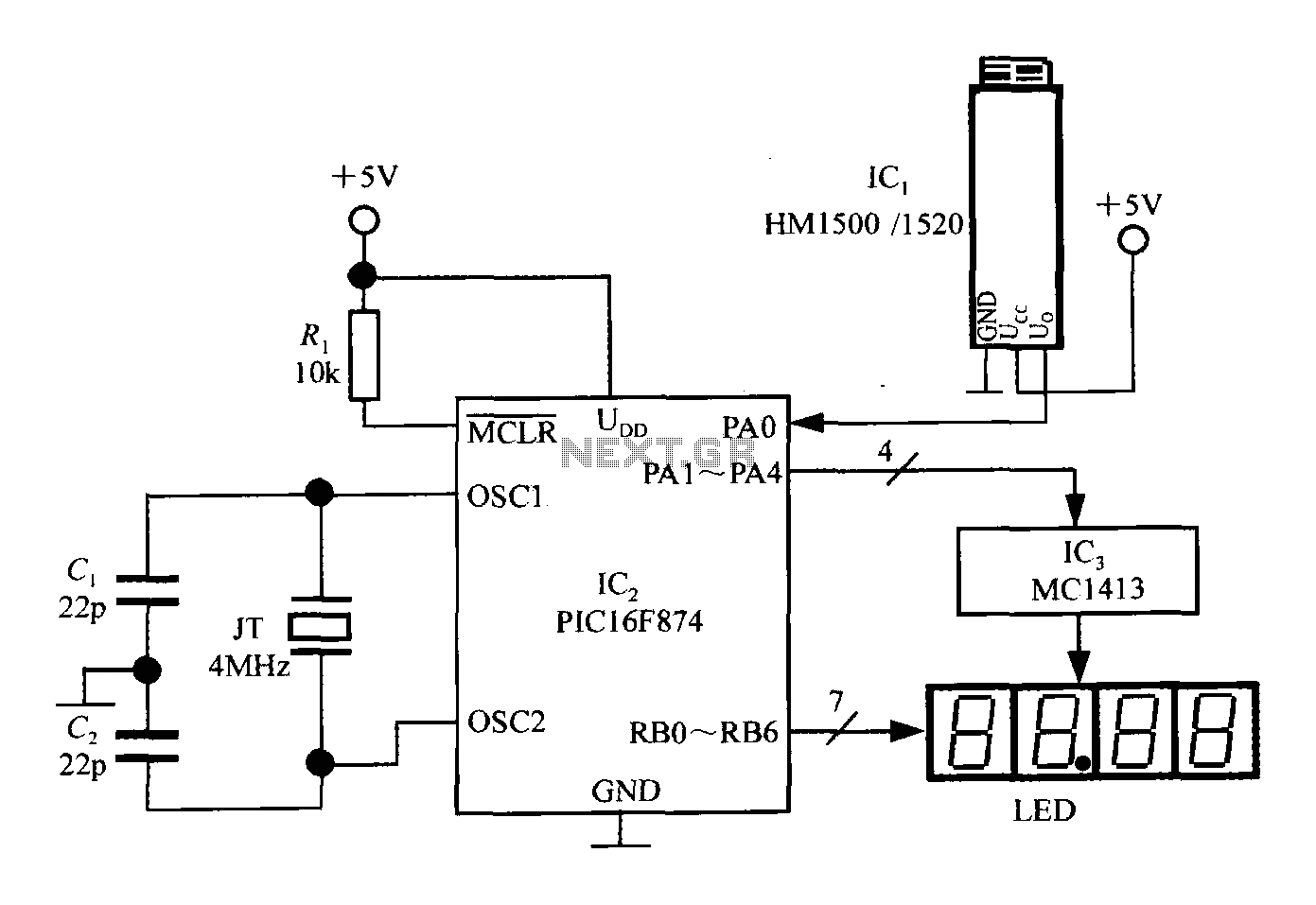
An intelligent humidity meter circuit utilizing the HM1500/1520 humidity sensor and a microcontroller configuration. The circuit operates on a +5V power supply and incorporates four common cathode LED digital displays. It employs three integrated circuits: IC1 is the HM1500/1520...
This is a line follower designed to trace grid-type tracks. It features five line sensors for tracking the line. This arrangement of five sensors has proven effective, having been used multiple times with successful results. The device is named...

The frequency pulses originating from the mains supply are safely insulated by capacitors C1 and C2, along with inductor L1. These pulses are amplified by transistor Q1, while diodes D1 and D2 limit any peak voltages at the input....
The previous version of this device used pulse width modulation (PWM) to control the power from the five solar panels to charge the battery bank. Under full sun conditions, the MOSFETs got a bit warm and the whole unit...