
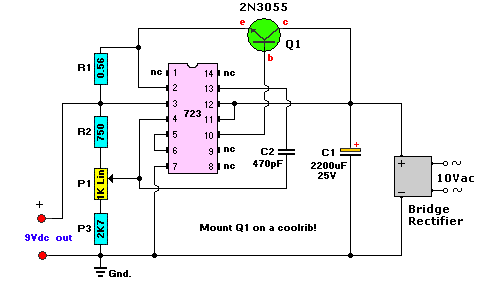
8 watts audio amplifier circuit

In audio amplifier circuits, the choice of potentiometer value for volume control is crucial for achieving optimal performance. Typically, a logarithmic (audio taper) potentiometer is preferred, as it provides a more natural response to human hearing. Common values for volume control potentiometers in audio applications range from 10 kΩ to 100 kΩ. The specific value chosen may depend on the input impedance of the amplifier and the desired range of volume adjustment.
The potentiometer should be connected in a voltage divider configuration. This involves connecting one terminal of the potentiometer to the audio signal input, the other terminal to ground, and the wiper (middle terminal) to the input of the amplifier. This setup allows the user to adjust the resistance in the circuit, effectively controlling the amplitude of the audio signal reaching the amplifier, thereby adjusting the volume output. It is important to ensure that the potentiometer is rated for the power levels present in the circuit to prevent damage and ensure reliable operation. Proper placement of the potentiometer in the circuit will also help minimize noise and interference, enhancing overall audio quality.what value of potentiometer will i use for the volume control of this audio amplifier circuit and in what place will i connect that? thank you.. 🔗 External reference
Related Circuits
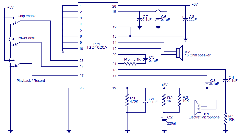
This circuit is designed in response to a request made by Mr. Vignesh for a voice recording and playback system. The circuit utilizes the ISD1020A IC from ISD, which is a CMOS single-chip record/playback device capable of recording voice...
The initial request was for a flexible preamplifier suitable for a high-end acoustic guitar equipped with a piezoelectric bridge pickup, while the second inquiry involved a preamp for a guitar emulator to introduce warmth reminiscent of vacuum tubes. Both...
Power an RS232-TTL converter circuit using the serial port to eliminate the need for an external power supply. It has been noted that the DTR, RTS, and TD pins can facilitate this. Since the TD pin is already utilized...
This AC to DC power supply can output 5A in continuous operation and 12A peak current. This type of DC power supply uses a PCB, allowing for two case types. The described AC to DC power supply is designed to...
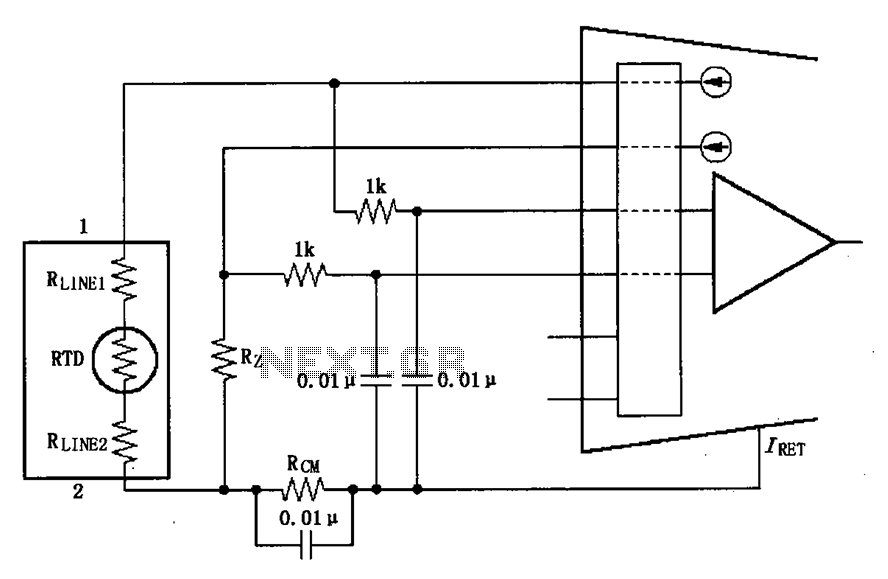
The long wire current loop transmission is susceptible to radio frequency (RF) interference, which can lead to errors in the sensitive input of the XTR108. This interference can occur particularly when the RTD sensor is located at a distance,...
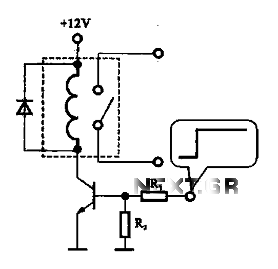
A relay control circuit is illustrated, which is commonly found in microwave switches. This circuit facilitates the operation of various components such as the power supply switch, electric fans, light bulbs, food turntables, and timers. The relay control signal...