
A relay control circuit

A relay control circuit is essential for managing high-power devices within microwave ovens and similar applications. The circuit operates by using a relay to isolate low-voltage control signals from high-voltage loads. The relay coil, when energized by a low-voltage signal, generates a magnetic field that actuates the relay contacts, allowing current to flow to the connected load. This method enhances safety by preventing high voltage from reaching sensitive control components.
The circuit can be constructed using either NPN or PNP transistors. In the NPN configuration, the transistor conducts when the base receives a sufficient control voltage, allowing current to pass from the collector to the emitter, thus energizing the relay coil. Conversely, in the PNP configuration, the transistor conducts when the base is pulled low relative to the emitter, allowing the current to flow from the emitter to the collector. This fundamental difference in operation necessitates careful consideration of the control signal applied to each type of transistor.
Protection diodes are crucial in this design, particularly when dealing with inductive loads such as relay coils. When the relay is de-energized, the collapsing magnetic field can generate a back EMF, potentially damaging the transistor. Therefore, a diode is placed in reverse bias across the relay coil to safely dissipate this induced voltage, ensuring the longevity and reliability of the circuit.
The schematic should clearly indicate the connections for each transistor type, the relay coil, and the associated protection diodes. Proper labeling of components and voltage levels will aid in understanding the operational characteristics of the circuit. This relay control circuit exemplifies an effective solution for controlling high-power devices while maintaining safety and minimizing component costs.A relay control circuit It shows the relay control circuit. There are many in the microwave switches, such as the power supply switch is turned on can be achieved, switch off p rotection can be achieved. In the microwave oven there are many components to be controlled, such as electric fans, light bulbs, food turntable, timers. In the relay control signal circuit which mostly belong to a strong signal, many of which are 22V of voltage.
If the direct control using a transistor switch, then the transistor must withstand high voltage 220 V, which must use high voltage transistors and power transistors. This circuit will not only increase production costs, but also security overhaul has also been guaranteed.
Because the high voltage of the transistor, current, it will inevitably need to add heat sink, the heat sink may be charged, the three legs of the transistor may also be charged, so it is very unsafe. Relays can be achieved by using low-voltage signal to control the high signal. It can be seen from the figure, in a relay coil is made of electromagnet, when energized electromagnet would be action, which led to open contacts close.
And contacts on the relay coil voltage is isolated, the control relay coil circuit does not have the high-pressure, very safe. Left and right in the figure on the circuit structure is the same, but uses different control transistor, using the left side of the circuit are NPN type transistors, the right side of the circuit using a PNP type transistor.
Polarity PNP transistor and the NPN transistor is not the same, so the use of PNP transistor circuit, the voltage to be applied to the emitter of PNP transistor, connected to the ground to relay this end. House of the drive signal also (NPN type transistor circuit) stated before the contrary, if the transistor is turned off, the circuit control signal is high, if the control signal appears low.
Transistor will be turned on, and then will flow through the relay 1V to control the turn on or off the relay contacts. Circuit in the connection of PNP transistors, polarity protection diodes designed also be reversed, because the coil generates an induced electromotive force polarity is changed, and when looking at the circuit diagram, pay attention to the model of the transistor.
Transistor models, the control signal, the voltage polarity protection diodes are not the same.
Related Circuits
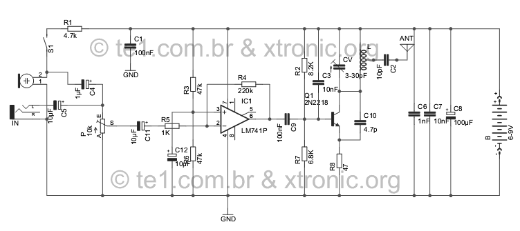
Evolution FM transmitter utilizing a 2N2218 transistor with an audio amplification stage using an LM741 operational amplifier. The design accommodates audio input from various sources such as MP3 players, MP4 devices, mobile phones, computers, and other audio sources, surpassing...
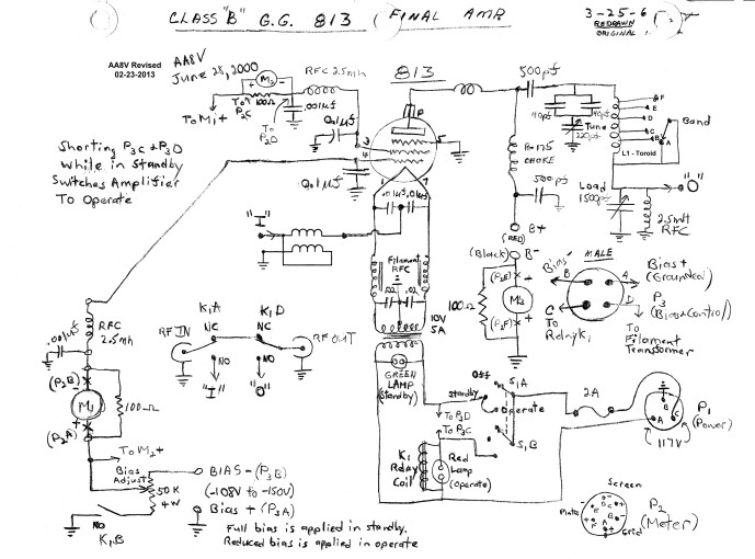
The input impedance of a grounded grid amplifier is typically several hundred ohms. While most vacuum tube transmitters can drive such an impedance without issue, solid-state transmitters, which are designed for loads close to 50 ohms, generally struggle with...
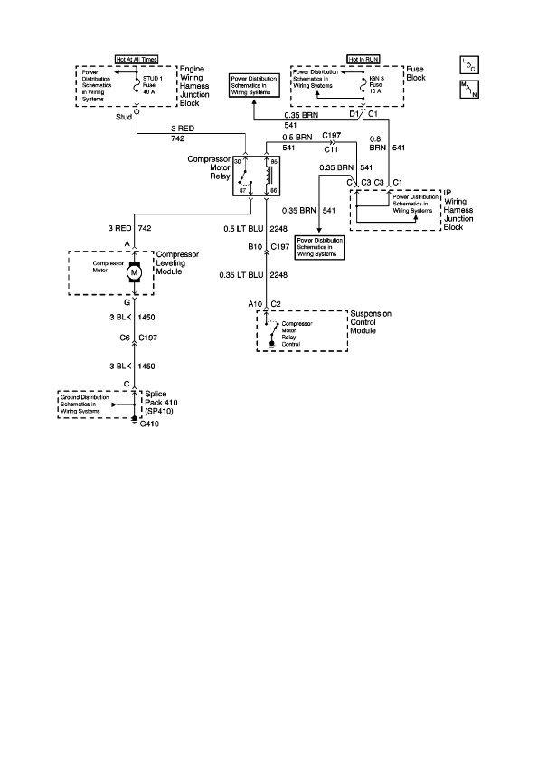
The physical location of the compressor relay is needed, as well as instructions on how to test the pressure sensor on the plastic tank of the compressor assembly. The exact location of the relay has not been confirmed, but...
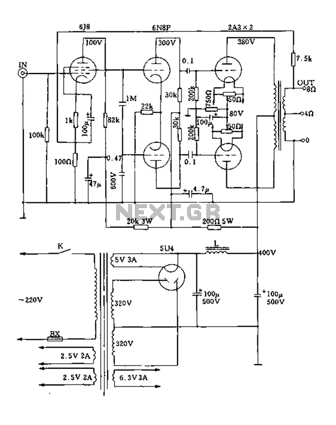
FIG. 2A3A is a low direct thermal resistance transistor with a resistance of only 800 ohms. The output transformer has a primary screen to load impedance of 3.5k ohms. The push-pull amplifier tube operates with a screen voltage ranging...
The heating element is connected in series with two back-to-back 16 amp silicon-controlled rectifiers (SCRs), which are controlled by a small pulse transformer. This pulse transformer features three identical windings; two of these windings provide trigger pulses to the...
The circuit diagram below illustrates a schematic designed to control the speed of a low-power induction motor, commonly found in fans. The schematic for controlling the speed of a low-power induction motor typically incorporates several key components that work together...