
8 Watts Audio Amplifier (TDA2003)
")
The described audio amplifier is a compact and efficient circuit designed for various audio amplification applications. It utilizes a minimal number of components, which contributes to its simplicity and ease of assembly. The amplifier is particularly suited for use as a booster in smaller audio systems, as a core component in more complex amplifier designs, or specifically as a guitar amplifier.
The amplifier operates within a voltage range of 12 to 18 volts DC, making it compatible with various power supply configurations. The choice of an 8-ohm speaker as the load allows the amplifier to deliver a maximum output power of approximately 8 watts. This output level is sufficient for driving small speakers in personal audio systems or for practice amplifiers in musical applications.
The design boasts a wide frequency response, which is crucial for maintaining audio fidelity across the audible spectrum. The low harmonic distortion rate of around 1.5% indicates that the amplifier can reproduce sound with minimal coloration, preserving the integrity of the original audio signal. This characteristic is particularly important in applications where sound quality is paramount, such as in music playback and live sound reinforcement.
In schematic form, the amplifier would typically include a gain stage, which may consist of a transistor or operational amplifier, followed by a driver stage that can efficiently drive the output load. Capacitors may be utilized for coupling and bypassing to ensure stable operation and to filter out unwanted noise. Resistors would be included to set the biasing conditions and gain levels of the amplifier circuit.
Overall, this audio amplifier presents a versatile solution for users seeking a reliable and straightforward amplification option, suitable for a range of applications from casual listening to musical performance.Nice small audio amplifier which use only few parts to give good quality sound. This amp can be used as a simple booster, the heart of a more complicated amplifier or used as a guitar amp. Although not perfect, this amplifier does have a wide frequency response, low harmonic distortion about 1.5%, and is capable of driving an 8 ohm speaker to output levels of around 8 watts with slightly higher distortion.
Any power supply in the range 12 to 18 Volts DC may be used.
Related Circuits
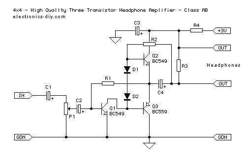
This is an improved version of a headphone amplifier I built many years ago. I wanted to share it because this simple circuit has done great service to me through all these years. It is very simple and reliable,...
The TX audio cable can be more complex than the RX audio cable. Typically, the TX audio cable requires a circuit to reduce the voltage from the sound card's LINE OUT jack; otherwise, the radio's transmit circuit may be...
This appears to be an infrared (IR) transmitter. IR signals do not penetrate walls, and it is assumed that this device is intended for use in a room separate from the one in which the user is located, rendering...
This is a design for a low noise microphone preamplifier, which is ideally suited to low impedance (600 Ohm nominal) microphones. One limitation is that it is not balanced, which is not a problem in a home recording environment,...
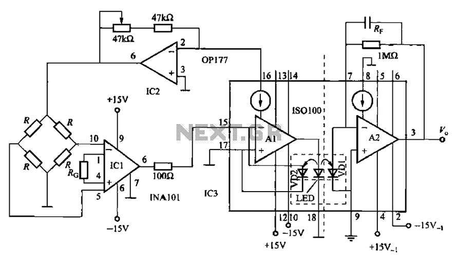
A bridge sensor output signal precision differential instrumentation amplifier with adjustable gain IC1 amplified signal IS0100. The gain of IC1 is determined by the external resistor Rc. The IC2 current source output is sent to drive the bridge sensor,...
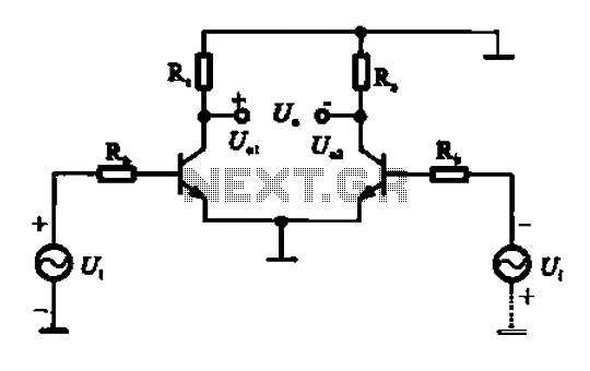
An amplifier circuit is designed to handle an assumed input consisting of two equal and opposite polarity signals, known as a differential mode signal. The two tube collector currents, Ic and IC7, are balanced in such a way that...