
Electronic Bicycle Horn Circuit

The electronic bicycle horn circuit operates by generating a square wave signal that produces an audible sound when activated. The core component, U1, is a Schmitt trigger which provides hysteresis, ensuring that the output transitions cleanly between high and low states, thus generating a stable square wave.
The circuit typically includes a power supply, which can range from 5V to 15V, depending on the design requirements. The input to the NAND gate is connected to a resistor-capacitor (RC) network that determines the frequency of the oscillation. The values of the resistor (R) and capacitor (C) can be adjusted to fine-tune the frequency, allowing for a customizable tone.
When the circuit is powered, the Schmitt trigger oscillates, producing a square wave output that can drive a small speaker or piezo buzzer. The output is connected to the speaker, which converts the electrical signals into sound waves. The sound produced is typically loud enough to serve as a warning signal for pedestrians and other cyclists.
Additional components may include a switch to activate the horn, and possibly a diode to protect the circuit from back EMF if an inductive load is used. The simplicity of this circuit makes it an effective solution for bicycle horns, providing a reliable and audible alert mechanism while maintaining low power consumption.
Overall, the design is compact and efficient, making it suitable for integration into various types of bicycles without significant modifications.This simple electronic bicycle horn circuit uses only one gate of a 4093 quad 2-input NAND Schmitt trigger, U1, conected in a simple, low frequency, square.. 🔗 External reference
Related Circuits
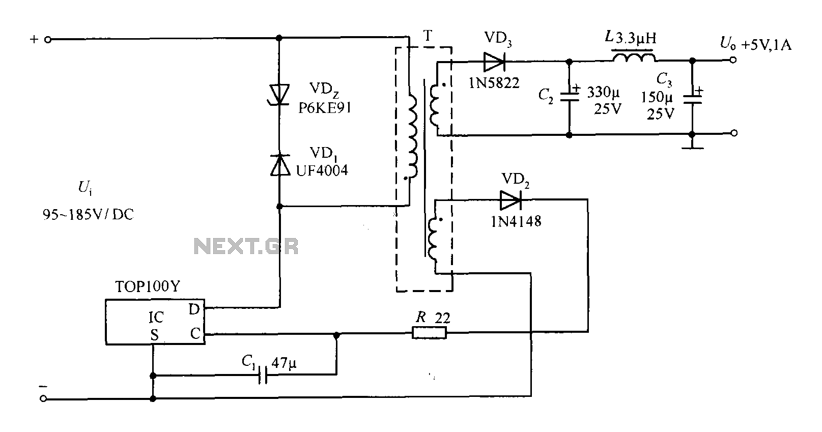
The TOP100Y is a flyback DC switching power supply circuit with a +5V, 1A output. This power supply features a feedback circuit that directly regulates the output voltage, making it suitable for applications that require electrical isolation and minimal...
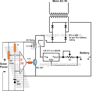
The automatic changeover relay circuit was requested by Mr. Karimulla Baig. The circuit is designed to charge a connected battery at a constant current using power from a solar panel. In the absence of solar energy, such as during...
The Wireless Keylogger consists of two main building blocks: the transmitter and the receiver. The actual keylogging takes place in the transmitter, which is in fact a PS/2 hardware keylogger, with a built-in 2.4 GHz wireless module. Captured keystroke...
The power supply has been simplified. Power transformers and rectifiers have been omitted, and some components from the MOSFET voltage regulator circuits have been removed, including 1N5242 zener diodes between the source and gate and 10k resistors in series...
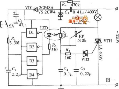
The diagram illustrates a lamp dimmer that gradually increases and decreases light intensity. This feature prevents sudden illumination, which can be a shock to the human eye, and also minimizes damage caused by inrush current when the lamp is...

This circuit is designed to detect the approximate percentage of salt contained in a liquid. After careful calibration, it provides a quick, rough indication of the salt content in liquid foods for dietary purposes. The circuit utilizes the LM324...