
A circuit of a pyroelectric infrared switch application BISS0001

The BISS0001 circuit operates by utilizing the pyroelectric infrared sensor to detect motion or heat changes in its environment. This is achieved through a two-stage amplification process where the signals from the sensor are first amplified by OP1, then further processed by OP2. The dual comparators, COP1 and COP2, ensure that only significant changes in the detected signal are passed through as trigger signals, effectively filtering out noise and irrelevant fluctuations.
The use of a photosensitive resistor (R3) adds an additional layer of functionality, allowing the system to adapt based on ambient light conditions. This feature is particularly useful for automatic lighting applications, as it prevents the system from activating in well-lit conditions, thereby conserving energy and reducing unnecessary wear on the connected devices.
The gain of the operational amplifiers can be fine-tuned using resistor R6, allowing for flexibility in circuit design based on specific application requirements. The choice of resistor values and capacitor sizes for the timing components (R9, R10, C6, and C7) directly influences the response time and delay characteristics of the system, enabling customization for different operational scenarios.
Overall, the BISS0001 integrated circuit provides a versatile solution for automatic control applications, combining sensor technology with intelligent signal processing to enhance user convenience and energy efficiency in various environments.BISS0001 is a sensor signal processing with higher performance integrated circuits, which together with the pyroelectric infrared sensors and a small amount of external components constitute passive pyroelectric infrared switch. It can automatically and quickly open various types of incandescent, fluorescent, buzzer, automatic doors, electric fans, dryers and automatic sinks and other devices, especially for enterprises, hotels, shopping malls, warehouses and family aisles, corridors and other sensitive area, or automatic lighting, lighting and alarm systems for the security zone.
FIG R6 can adjust the size of the gain of the amplifier, the original drawings selected 10K, actual use can 3K, can improve the gain of the circuit to improve circuit performance. Output delay time Tx by an external R9 and sizing C7 triggered by an external blocking time Ti R10 and C6 resizing, R9 / R10 470 ohms may be used, C6 / C7 can choose 0.1U.
Related Circuits
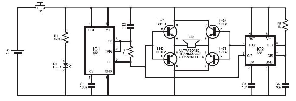
This ultrasonic sensor circuit consists of a set of ultrasonic receivers and transmitters that operate at the same frequency. When an object moves within the covered area, the circuit's balance is disturbed, triggering the alarm. The ultrasonic circuit is...
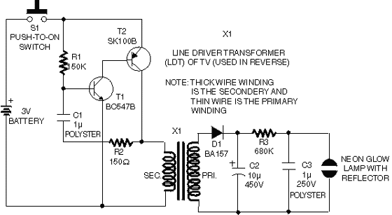
This circuit operates on 12V DC instead of mains AC. This is an advantageous approach for those who prefer not to deal with circuits connected directly to mains voltage or wish to power the stroboscope using batteries. Flash Slave...

A 40673 dual-gate MOSFET is matched to a crystal filter operating at 45 MHz. The filter impedance is approximately 2 kΩ. The +4 V source can be adjusted to control the gain, ranging from +4 V to -4 V. The...
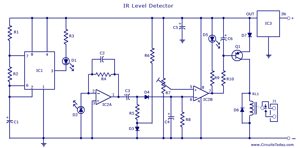
An infrared (IR) sensor or detector circuit diagram utilizing a 555 integrated circuit (IC), primarily employed as a water level or liquid level sensor and proximity detector circuit. The described circuit employs a 555 timer IC configured in a monostable...
A 2 x 18W Hi-Fi Stereo Power Amplifier is designed using two TDA2030 integrated circuits (ICs). This amplifier features excellent input sensitivity, low distortion levels, stable operation, and comprehensive protection against overloads and output short circuits. It can serve...
The adjustment potentiometer RP can modify the magnitude of the DC output voltage. The adjustment potentiometer, designated as RP, is an essential component in various electronic circuits, particularly in power supply systems and signal conditioning applications. It serves as a...