
80 milliwatt Improved 3 Transistor Audio Amp
The described circuit employs a positive feedback mechanism to enhance the output amplitude, making it suitable for driving small speakers in low-power applications. The configuration is particularly effective for audio amplification in compact devices such as radios. The use of a 25-ohm speaker indicates that the circuit is designed for low-impedance loads, which can be beneficial in portable applications where efficiency and power conservation are essential.
The circuit's design incorporates a 1K load resistor connected to the speaker, which plays a pivotal role in the feedback loop. As the output signal fluctuates, the interaction between the speaker and the load resistor allows for improved transistor switching, enhancing the overall performance of the amplifier. The inclusion of a 470 µF capacitor is critical for stabilizing the voltage across the transistors during operation, ensuring that the circuit can handle dynamic audio signals without significant distortion.
The choice of transistors, such as the 2N3053 and 2N2905, provides flexibility in the design, allowing for various alternatives based on availability and performance requirements. It is advisable to consider the thermal characteristics of the selected transistors to prevent overheating, especially under continuous load conditions. The circuit's idle current specification ensures that the transistors operate within their safe limits, maintaining reliable performance over time.
For further optimization, careful selection of the feedback resistor is crucial. This resistor influences the gain of the amplifier and the overall output voltage swing. By adjusting this component, designers can tailor the circuit to specific applications, ensuring that it meets the desired performance criteria while minimizing distortion and maximizing efficiency.
Overall, this circuit represents a practical solution for low-power audio amplification, combining effective feedback mechanisms with component flexibility to achieve satisfactory performance in small electronic devices.This circuit is similar to the one above but uses positive feedback to get a little more amplitude to the speaker. I copied it from a small 5 transistor radio that uses a 25 ohm speaker. In the circuit above, the load resistor for the driver transistor is tied directly to the + supply. This has a disadvantage in that as the output moves positive, the drop across the 470 ohm resistor decreases which reduces the base current to the top NPN transistor. Thus the output cannot move all the way to the + supply because there wouldn`t be any voltage across the 470 resistor and no base current to the NPN transistor.
This circuit corrects the problem somewhat and allows a larger voltage swing and probably more output power, but I don`t know how much without doing a lot of testing. The output still won`t move more than a couple volts using small transistors since the peak current won`t be more than 100mA or so into a 25 ohm load.
But it`s an improvement over the other circuit above. In this circuit, the 1K load resistor is tied to the speaker so that as the output moves negative, the voltage on the 1K resistor is reduced, which aids in turning off the top NPN transistor. When the output moves positive, the charge on the 470uF capacitor aids in turning on the top NPN transistor.
The original circuit in the radio used a 300 ohm resistor where the 2 diodes are shown but I changed the resistor to 2 diodes so the amp would operate on lower voltages with less distortion. The transistors shown 2n3053 and 2n2905 are just parts I used for the other circuit above and could be smaller types.
Most any small transistors can be used, but they should be capable of 100mA or more current. A 2N3904 or 2N3906 are probably a little small, but would work at low volume. The 2 diodes generate a fairly constant bias voltage as the battery drains and reduces crossover distortion. But you should take care to insure the idle current is around 10 to 20 milliamps with no signal and the output transistors do not get hot under load.
The circuit should work with a regular 8 ohm speaker, but the output power may be somewhat less. To optimize the operation, select a resistor where the 100K is shown to set the output voltage at 1/2 the supply voltage (4. 5 volts). This resistor might be anything from 50K to 700K depending on the gain of the transistor used where the 3904 is shown.
🔗 External reference
Related Circuits
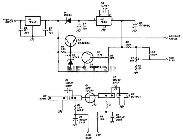
Using an NEC70083, this 1296-MHz amplifier provides approximately 17 dB of gain with a noise figure ranging from 1 to 1.5 dB. It is built on a G-10 epoxy fiberglass printed circuit board (PCB). Adhering to the specified layout...
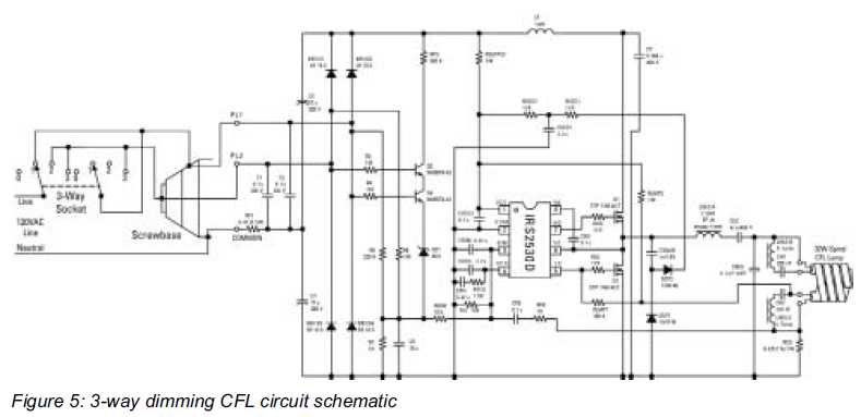
The dimming function introduces a new range of applications for compact fluorescent lamps (CFLs). Compact fluorescent lamps are rapidly replacing incandescent light bulbs due to their energy efficiency and longevity. The integration of dimming capabilities into compact fluorescent lamps significantly...
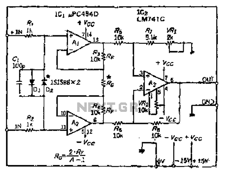
All resistance values are equal, resulting in the Cantonese operational amplifier's gain (A) being equal to 1. However, by selecting smaller resistances, the gain can be adjusted. The circuit can achieve the desired gain through six configurations. Two heavy...
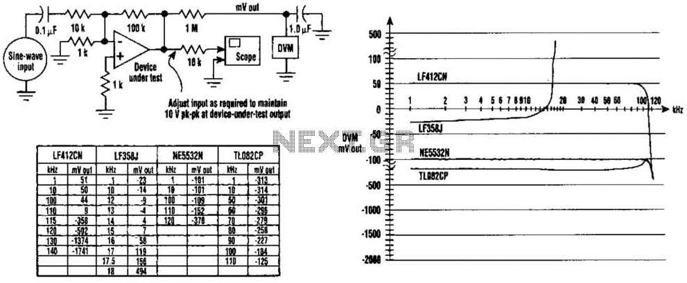
The DC values of op-amp offsets cannot always be assumed to remain constant when delivering AC outputs. No device is perfectly symmetrical in terms of maximum positive slew rate compared to maximum negative slew rate. As a result, there...
This reference design demonstrates the MAX98400 Class D audio amplifier in a stereo audio docking station application. The demo box is a powered speaker dock that drives a speaker system consisting of 2-inch satellite speakers and a 5-inch subwoofer. The...
The video amplifier depicted in the diagram is a widely recognized design that is both simple and highly effective. However, the transistors are susceptible to damage if the potentiometers (black level and signal amplitude) are set to their extreme...