
interfacing relay 8051 keil c

In the context of electronic circuits, relays serve as crucial components for controlling high power devices while maintaining the integrity of low power control circuits. The operation of an electromagnetic relay is based on the principles of electromagnetism. When the relay coil is energized, it generates a magnetic field that attracts a movable armature, closing or opening the contacts of the relay. This action allows the relay to control the flow of electricity in a high power circuit without exposing the low power control circuit to high voltages or currents.
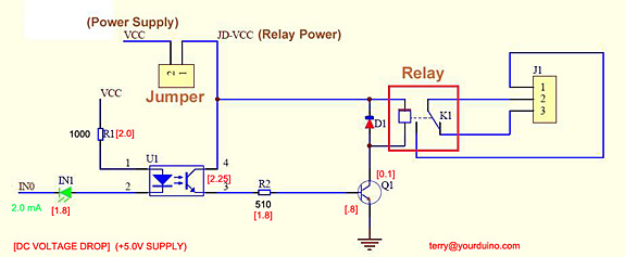
To implement a relay in a circuit, a transistor is often employed as a switch. The transistor acts as an intermediary, amplifying the current from the microcontroller to drive the relay coil. In this configuration, a resistor is placed in series with the base of the transistor to limit the current flowing into it, ensuring that the transistor operates within its safe limits. The relay coil is connected to a higher voltage supply, which allows it to draw the necessary current to activate the relay.
It is essential to consider the specifications of both the relay and the microcontroller when designing the circuit. The relay's coil voltage and current ratings must match the supply voltage used, while the transistor must be chosen based on its ability to handle the required current and voltage levels. Additionally, flyback diodes are commonly used in relay circuits to protect the transistor and microcontroller from voltage spikes generated when the relay coil is de-energized.
In summary, the integration of relays into electronic circuits provides a reliable means of controlling high power devices, ensuring that low power control systems remain safe and effective. Proper circuit design, including the use of transistors and protective components, is vital for the successful implementation of relay-based control systems.In some electronic applications we need to switch or control high voltages or high currents. In these cases we may useelectromagnetic or solid state relays. For example, it can be used to control home appliances using low power electronic circuits. Anelectromagneticrelayis a switch which is used to switch High Voltage or Current using Lowpower circuits. It magnetically isolates low power circuits from high power circuits. It is activated by energizing aelectromagnet, coil wounded on a soft iron core. For detailed working of relay please visit this page. A relay should not be directly connected to a microcontroller, it needs a driving circuit due to the following reasons. A microcontroller will not able to supply current required for the proper working of a relay. The maximum current that A89C51 microcontroller can source or sink is 15mA while a relay needs about 50 100mA current.
Transistor is wired as a switch. which drives the relay. When the first pin of port P2 goes high the base current flows through the 10k resistor. This in turn switches the transistor ON. The relay gets enough current through the 12v supply to switch the secondary circuit ON. 🔗 External reference
Related Circuits
Control a relay from an Arduino-compatible board. When attempting to activate the relay from the Arduino, it takes at least a second to close, and sometimes it does not close at all. Digital pin 2 of the Arduino is...

After the turn-off circuit is first applied to the next KA KA, the intermediate interval required is less than Is. This is due to the time needed, which is equal to three times the charge time constant of the...
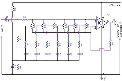
The circuit functions as a light detector. Under normal conditions, the resistance of the light-dependent resistor (LDR) is high, which keeps pin 2 low. When light falls onto the LDR, the resistance decreases to a few hundred ohms, triggering...
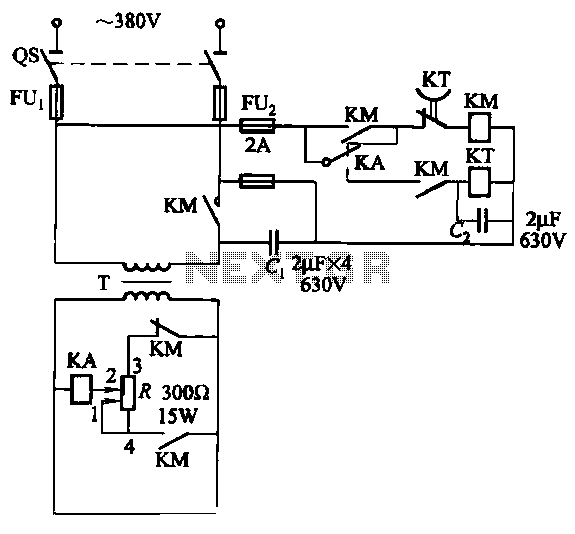
The relays in the AC arc welding machine manage the load through a three-way power circuit, as depicted in Figure 522. The selected relay type is KA, operating at 24V. Additionally, the time relay KT is of the JS7...
A 3V battery-operated, small portable unit designed to activate a relay through a hand clap. Subsequent claps will deactivate the relay. This circuit utilizes a microphone as a sound sensor to detect the sound of a hand clap. The microphone...
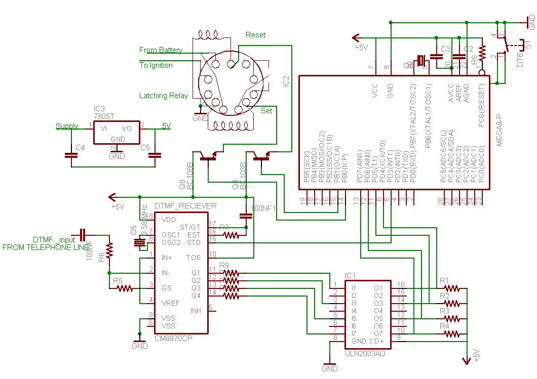
This document outlines the process of interfacing a microcontroller with a phone line. The tones generated when dialing numbers on a phone can be utilized to remotely control various devices. It provides guidance on incorporating Dual-Tone Multi-Frequency (DTMF) tones...