
80M CW QRP rig

The project emphasizes the importance of careful planning and component selection in amateur radio rig design. The use of a protoboard allows for iterative testing and refinement of the circuit before committing to a PCB layout. The choice of the MC3362 IC as the core of the receiver highlights the need for reliable components in RF applications. The adjustments made to the IF and VFO frequencies demonstrate the iterative nature of circuit design, where performance improvements are sought through experimentation.
The challenges faced, particularly with VFO stability, underline common issues in RF design, such as drift caused by temperature variations and component tolerances. The use of specific capacitors for compensation illustrates the practical knowledge gained from the amateur radio community, showcasing the collaborative spirit of the hobby. The successful completion of the project and the positive reception reports serve as a testament to the effectiveness of the design choices made throughout the process.
Overall, the "Aquarius-80" project exemplifies the blend of creativity, technical skill, and perseverance that defines successful amateur radio construction, culminating in a functional rig capable of making meaningful contacts within the amateur radio community.After some time of no building activity, the dark afternoons and less busy week-ends has come finally. Perfect time of the season to build a new rig. See what is being done on my bench. I like this way of start, because of easy modelling a components layout. Say, that`s enough experiments with NE612. The heart of the receiver is popular Motorola c hip MC 3362. Not much Ham applications are available. That`s my pleasure to go. This is very convenient and gives opportunity to select best circuit, best value and best component. I have changed IF frequency as well as VFO frequency triple times. Finally remained on 8MHz RF and corresponding VFO, which seems to be very stable. I don`t have final schematic because there are so many ways to develope. My favourite "universal breadboard" has changed into protoboard, but I am trying to develope future printing circuit based on above "training". Every component is carefuly selected and placed. Schematic diagram is corrected in parallel. The biggest problem was the VFO stability. I had to recall experience of many Hams and myself to find a solution for drifting parameters of coil, capacitors and IC`s internal varactor diode.
Compensation wasn`t easy but finally I used poly cap, T50-6 ( yellow core works better than red) and ceramic trimmer capacitor. The overall drift is very low. 170 Hz within first 5 minutes and less than 50Hz in following hours. I tried varactor tuned four crystal ladder filter for the first time. Works fine The Contest ended with satisfactory score - 312 QSOs, 34(!)zones and 82 countries only. This counts for 95k points. Just after the contest I decided to eventually finish prototyping and commence PC board project for future kit.
Below you can see working prototype-clean. I worked OK1DSS today (11th of December) receiving solid 579 report. Sigi from Desna hasn`t problem copying all QSO data, so did I. ARRL 10m Contest failed and I spent week end mostly on mechanical work, putting a board into metal case. All rig measures WxDxH - 100mmx140mmx50mm. After wiring all front and rear components and plugging a 13, 8V DC everything appeared to be mute. That was a thrill, because both protoboards worked fine. Couple of minutes and short cut in headphones socked cleared everything. New problems appeared instead. This is my probably last attempt to build RF project on computer based predrilled boards. Too many stray capacitances ( antennas ! ), poor grounding etc. The next step will be a home brew PC board with rather different components layout. Anyway, another contacts were made confirming that 3Watts is enough for 80m Europeans and finishes the author`s job.
I was thinking of the name of this rig. How about " Aquarius-80 " - which obviously refers to my personal astro sign. I drew a serious PC Board using simple software from Express PCB. This was my first trial, and after couple of hours I made it. The picture of PCB was exported to Corel Photo Paint for adjustment and printing on the foil. Using thermotransfer method and house iron I broke two sheets of foil, but third came quit good requiring minor corrections. Drilling more than 100 holes produced nice blister on my hand, but that was really worth it !. Today ( 30th of December) I successfuly assembled RX side, QSK and sidetone, writing "step by step" manual in parallel.
This will help someone easy assembling of the rig. Let`s suppose in one week-end ;-) New Year has come with light snow and completely assembled "Aquarius" board. No problems appeared and my newest rig could produce clean 5W output signal. The first QSO is always a great moment in Ham`s life. This time the first contact was made with Guyla HA7JCA from Szentendre. He gave me 589 with no negative comments on signal quality. So, after several weeks another rig became alive. What is to be done: packing into case, homebrewing front panel silkscreening and that`s it. The rig reached it`s final look. 🔗 External reference
Related Circuits

Mains-triggered musical doorbell using the musical IC UM3482 circuit diagram, featuring various and unique doorbell projects. The mains-triggered musical doorbell circuit utilizes the UM3482 integrated circuit, which is specifically designed for generating musical tones. This circuit is activated by a...
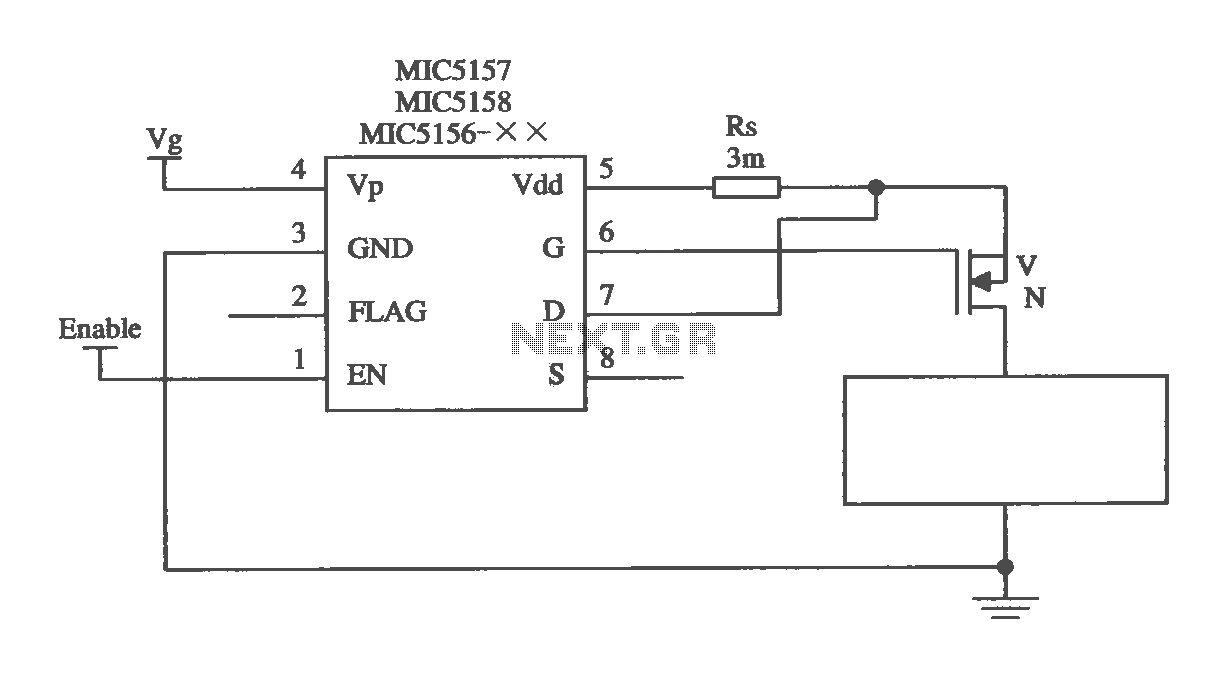
The MIC5156 is a device that incorporates a current limiting function, allowing it to handle high output currents. It can operate with or without a switching regulator circuit. The S terminal is left vacant, and a 16V Zener diode...
This ultra-bright white LED lamp operates on 230V AC with low power consumption. It is suitable for illuminating VU meters, SWR meters, and similar applications. The ultra-bright LEDs available in the market range from Rs 8 to 15. These...
This is a high-brightness LED driver circuit. To provide a constant-voltage output, DC/DC regulators are typically used. However, a constant-current output is the preferred method for driving LEDs. The high-brightness LED driver circuit is designed to efficiently manage the power...
Normally the active high output from the inverter is used to enable the remainder of the CMOS gates which then perform some useful function. When the SIMD1 triggers at night, it snaps on and the output signal can be...
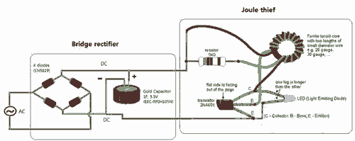
Breathe down and come out on the bright flashlight. In order to promote the voltage, pieces of a highly skilled Joule thief circuit have been used. The Joule thief circuit is a minimalist, low-power boost converter designed to extract energy...