
Bright JOULE THIEF flashlight circuit

The Joule thief circuit is a minimalist, low-power boost converter designed to extract energy from low-voltage sources, such as depleted batteries. This circuit is particularly effective in applications where energy efficiency is critical, allowing for the utilization of energy that would otherwise be wasted.
The core component of the Joule thief is a transistor, which acts as a switch. When the circuit is powered, the transistor rapidly turns on and off, creating a magnetic field in the inductor. This magnetic field stores energy and, when the transistor turns off, the collapsing field induces a voltage spike. This spike is then rectified and smoothed to provide a higher output voltage than the input.
The typical configuration includes a few essential components: a transistor (often a low-threshold NPN type), a resistor, an inductor, and a diode. The resistor is used to limit the base current to the transistor, ensuring it operates within safe limits. The inductor is chosen based on the desired output voltage and current, while the diode prevents backflow of current, protecting the circuit.
In a flashlight application, the Joule thief can significantly extend the life of batteries by allowing them to be fully utilized until they can no longer provide usable power. This is particularly advantageous for LED flashlights, which require higher voltages than what a single AA or AAA battery can provide when nearly depleted.
Overall, the Joule thief circuit exemplifies an efficient solution for low-voltage energy harvesting, making it an ideal choice for portable lighting applications where maximizing battery life is essential.Breathe down and come out on the bright flashlight. In order to promote the voltage, I have used pieces of highly skilled Joule thief circuit 🔗 External reference
Related Circuits

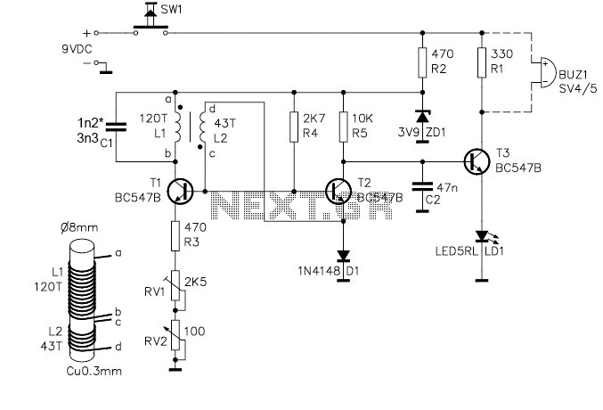
The circuit diagram of a lantern dimmer/flasher designed by Tony Van Roon includes the following electronic parts: R1 = 100K, R2 = 100K, R3 = 100K, R4 = 100K, R5 = 3.9K, R6 = 3.9K, R7 = 470, R8...
The project demonstration has been successfully completed, with the only remaining task being the final project report due on June 15, which will be integrated with a conference paper. This update marks the last entry in the electronic notebook,...
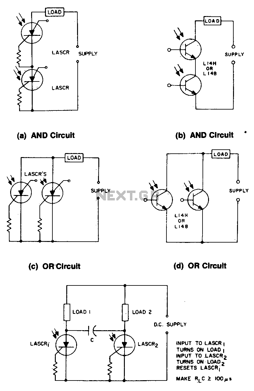
These circuits illustrate some of the common logic functions that can be implemented. The provided circuits serve as examples of fundamental logic functions utilized in digital electronics. Logic functions are the building blocks of digital systems, enabling the execution of...
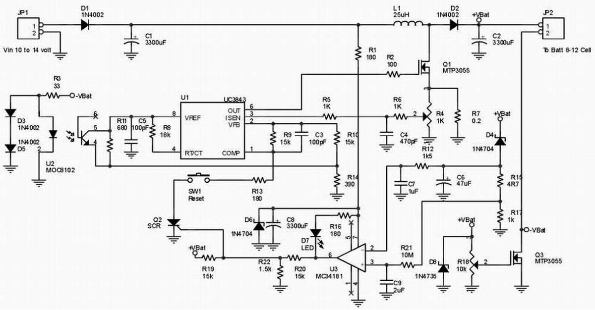
This is a NiMH battery charger using the IC LTC4060, which is powerful, effective, and efficient. The LTC4060 IC specializes in NiMH battery charging, ensuring safe operation with features such as battery temperature protection during charging. It includes a...
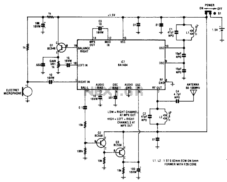
The circuit utilizes Q1 to buffer the right-channel balance output, while Q2 and Q3 create a VOX circuit. When the microphone signal level increases, the VOX output also rises, causing the multiplexer within IC1 to route the high-gain left-channel...

This design circuit functions as a sine wave oscillator, providing both sine and square wave outputs across a frequency range from below 20 Hz to above 20 KHz. The oscillation frequency can be easily adjusted by varying a single...